
|
|
Forum Index : Microcontroller and PC projects : Static/emergency display using VT100....
| Page 1 of 2 |
|||||
| Author | Message | ||||
Grogster Admin Group Joined: 31/12/2012 Location: New ZealandPosts: 9975 |
I have developed a board using the VT100 and a PICAXE 08M2 chip. The PIC32 handles the VT100 side of things, and the PICAXE chip basically just acts as a serial memory of sorts, allowing you to setup a screen(using all the VT100 codes etc), which is then sent to the VT100 PIC32 chip. The idea being for a pre-programmed VGA display screen for certain applications. I developed this, as I needed a specific screen to show on the VGA when my main system was in remote-access mode via the WAN. When this is requested, an electronic KVM switch is tripped by the main system, which then switches to the display message shown by this unit. Once remote-access is completed, the system reverts to the standard VGA supplied by the MaxiMite based system. Bench-testing is working great. Not sure if this can be useful for others or if it is really more specific to MY needs, but there you go. Board is 50mm square, including the VGA socket, baud-rate pads, colour select pads, PICAXE 08M2 message store, LED's etc. In my case, I selected RED as the colour for the VT100 used in this way, as red is often used to indicate something important or something needing attention etc. Using iTead Studio, you can get 10 of these boards for only US$9.90 Here is a quick photo: 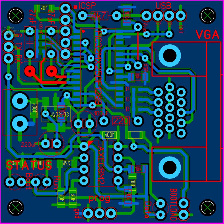
EDIT: This is still a work in progress. Although the test version works fine on the breadboard, I have yet to actually get these PCB's made - I should clarify that point... Smoke makes things work. When the smoke gets out, it stops! |
||||
| hitsware Guru Joined: 23/11/2012 Location: United StatesPosts: 535 |
I'm missing something real basic here..... When you 'talk' to the PicAxe, what language do you use ? PicAxe Basic ? I have a few of those 08M2. |
||||
TassyJim Guru Joined: 07/08/2011 Location: AustraliaPosts: 6538 |
The picaxe is programmed as normal with a series of long strings which gets sent to the VT100 terminal through the serial port. The strings contain all the VT100 escape codes to give a pretty display on the terminal. The VT100 terminal is one of Geoff's terminal in a PIC. This resulting display is used to replace the usual VGA data coming from a PC. The changeover is done using a KVM switch. I think that covers it. Jim VK7JH MMedit |
||||
| Grogster Admin Group Joined: 31/12/2012 Location: New ZealandPosts: 9975 |
Yes, that's it, Jim. 
The main system, running on a colour MaxiMite is also routed through the two port KVM switch. The KMV switch is opened up, and wires run from the button on the top(which selects which VGA/KB/M are connected) back to a relay on the main board, so that the main system can switch the VGA to the "Remote administration mode" message controlled by the board above, and this also has the effect of disconnecting the KB from the MaxiMite(via the same KVM switch), so no-one on site can use the KB to upset what I am trying to do remotely. In the case of the KB, it is really more of an isolation switch, more then anything else. Some of you may well be wondering why I used a PICAXE, and not the fabulous new Micromite chip. The reason was PCB space and available stock. The 08M2 is a better fit then another 28-pin SOIC, and I still have 10 or so 08M2 chips in DIL format, so that was why I did it that way. The 08M2 can also run at 3v3, meaning I can directly connect the 08M2 and the VT100 PIC32 directly without any level correction or additional resistors. The 08M2 has 2KB of memory, which is plenty for lots of screen setup strings. This 50mm module can also be used like the normal VT100 unit, if you don't install the PICAXE chip. The three-way header at the top left is are the standard TXD/RXD/GND connections to the VT100, albeit with no allowance for >3v3 input. There is also a header for USB, so that updating the firmware via USB is also possible, albeit with a slightly customized cable. I am looking at swapping that header for a mini-USB connector, once I find some... Smoke makes things work. When the smoke gets out, it stops! |
||||
| hitsware Guru Joined: 23/11/2012 Location: United StatesPosts: 535 |
So it's way more complicated than simply connecting the VT-100 circuit to an off the shelf 08M2, a keyboard, and a monitor, and coming up in PicAxe Basic ? |
||||
| Grogster Admin Group Joined: 31/12/2012 Location: New ZealandPosts: 9975 |
If you are thinking of using this arrangement to act as a programmer for PICAXE BASIC, then no, it won't work that way. PICAXE uses and expects a programming IDE application - you can't program the PICAXE using a terminal. However, once the PICAXE is programmed, you can then stream data to the VT100 terminal, and that is what I am doing. Smoke makes things work. When the smoke gets out, it stops! |
||||
| hitsware Guru Joined: 23/11/2012 Location: United StatesPosts: 535 |
Oh well .... 
Not to digress, but that KVM switch can fix me up ! I didn't realize such a thing was made that cheaply. I should be able to hook my Linux PC to 1 channel, my ColorMaxiMite to the other, and not have to worry about terminal emulators etc.... 
I'm going to make one of the VT100 boards so that should allow me to handle the MicroMite also .......  |
||||
| Grogster Admin Group Joined: 31/12/2012 Location: New ZealandPosts: 9975 |
It was a nice idea, hitsware, so don't be discouraged. It's simply that the PICAXE does not talk that way for programming purposes, and you need the Programming Editor(PE) IDE software - but I have never seen that as a hassle, really. The Micromite, on the other hand, is designed to use a terminal emulator for programing etc, and so that is why it works for that chip.
I found my KVM switch on eBay, and paid about US$17 for it. Comes from China, surprise, surprise. My one was just a two-port one, and was VGA and PS/2. If You are getting one, make sure you look for the PS/2 ones, not the USB ones. Smoke makes things work. When the smoke gets out, it stops! |
||||
| hitsware Guru Joined: 23/11/2012 Location: United StatesPosts: 535 |
> you need the Programming Editor(PE) IDE software - Another thing I can't get to work in Linux ..... I could program the PicAxes on my in house XP system and then take them back to the laboritory and plug them into the MaxiMite for multiple pwms I guess. (might be a problem getting them all in tune (separate xtals)) ? |
||||
| robert.rozee Guru Joined: 31/12/2012 Location: New ZealandPosts: 2528 |
what could be quite neat would be to have the ability to have several message screens stored, and switch between them based upon the inputs to one or more pins on the PICAXE. you could then have several levels of 'alert'; an added set of relays (or a CD4066) could also switch the screen colour. rob :-) |
||||
| Grogster Admin Group Joined: 31/12/2012 Location: New ZealandPosts: 9975 |
@ hitsware - There is AXEpad for Linux, but I had issues getting it working in Linux too. I currently have PE5 on my Win8 box, and it works fine. @ robert.rozee - I will see if I can add that by way of external pin. You could have several messages selected by buttons on an ADC string of resistors a-la the "12 buttons on one input" concept. There are currently two I/O's on the PICAXE I am not using, and have just tied them to deck with 10k resistors, so I could use one of those. Smoke makes things work. When the smoke gets out, it stops! |
||||
| Grogster Admin Group Joined: 31/12/2012 Location: New ZealandPosts: 9975 |
Here is updated image: 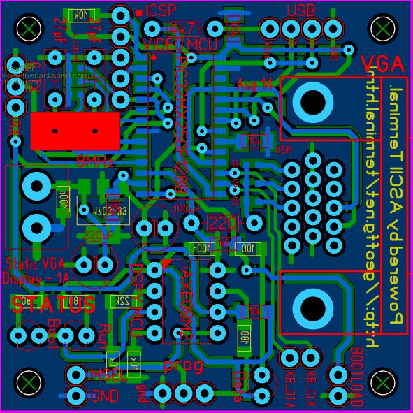
This PCB now contains keyboard data and clock pins, although I just could not find out how to squeeze in the two pull-up resistors + 5v supply for the KB, so these are just the two main pins. Using a KB would be easy enough, with the addition of a 5v supply and resistors across the CLK and DTA lines back to the module - real estate is getting pretty scarce on this board now! 
Board also now has provision for multiple messages using a string of buttons on an ADC pin of the PICAXE - you could program several messages into the PICAXE, and select the one you wanted with buttons. Currently no way to select colour - it will have to remain fixed. With a bigger PCB, we could squeeze in the 4066 idea of Rob's, but not on this board! Smoke makes things work. When the smoke gets out, it stops! |
||||
bigmik Guru Joined: 20/06/2011 Location: AustraliaPosts: 2981 |
Groggy, You can always mount standard 1/4w resistors vertically, that way the legs can be spread what ever distance is needed to make a connection, ie. one res can have 0.1" spacing and another could be 0.2" if you cant space closer.. Can you post a pic of the bottom layer to see what the tracking looks like in that area? Mick Mick's uMite Stuff can be found >>> HERE (Kindly hosted by Dontronics) <<< |
||||
| TassyJim Guru Joined: 07/08/2011 Location: AustraliaPosts: 6538 |
Grogster, On my KVM switch, it has the ability to trick the computer into thinking a monitor IS connected at all times. I am not sure how it does it so the VT100 terminal might not get fooled but it is worth trying without the extra resistor on pin 12. Jim VK7JH MMedit |
||||
| Grogster Admin Group Joined: 31/12/2012 Location: New ZealandPosts: 9975 |
@ Mick: Here is the C2 layer and it's overlay. 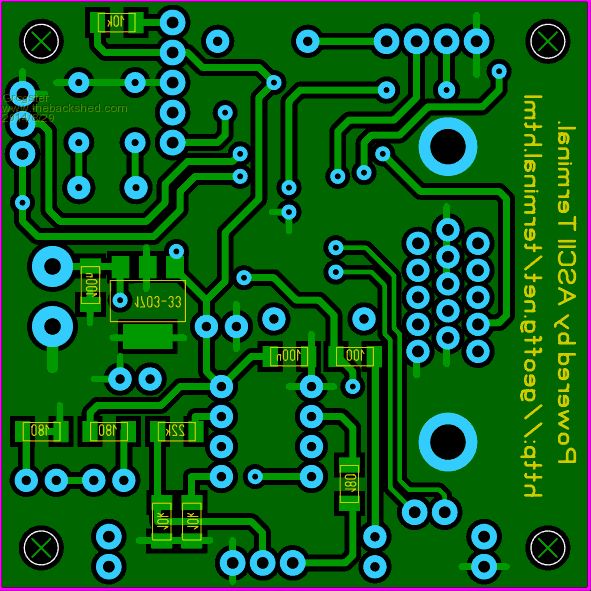
Please note that in this board, BOTH the top and bottom ground-planes are at ground potential. The top copper layer GP is not at 3v3, as might be expected with a double-sided GP board. @ Jim: Yes, that's a point. I will build the board without the 1k8 and try it. I have pulled my breadboard arrangement to bits now.  Smoke makes things work. When the smoke gets out, it stops! |
||||
| Grogster Admin Group Joined: 31/12/2012 Location: New ZealandPosts: 9975 |
Just a quick note here - PCB Zone in NZ - 10 pcs of double-sided PCB @ 50 x 50 = NZ$178 + GST + Postage. iTead Studio - 10 pcs of double-sided PCB @ 50 x 50 = US$9.90 + Postage. ...makes you wonder how the hell iTead can do it for the price. Smoke makes things work. When the smoke gets out, it stops! |
||||
| bigmik Guru Joined: 20/06/2011 Location: AustraliaPosts: 2981 |
Grogster, You can do some minor alterations and get the pullups for the keyboard on. See this mockup.. just a quick photoshop shove job. Mick 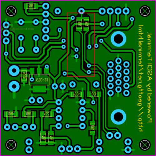
Mick's uMite Stuff can be found >>> HERE (Kindly hosted by Dontronics) <<< |
||||
| Grogster Admin Group Joined: 31/12/2012 Location: New ZealandPosts: 9975 |
Whose a clever boy, then? (rhetorical!)
VERY well spotted. I will add this to the layout. EDIT: This will ONLY work, if USB is connected, as you are tapping into the +5v Vbus of the USB connector. However, I think I can rework this idea. Smoke makes things work. When the smoke gets out, it stops! |
||||
| bigmik Guru Joined: 20/06/2011 Location: AustraliaPosts: 2981 |
Grogster, Now would you like me to add a Triode or Pentode Valve for you? 
One thing I have learned by doing PCBs is that no matter how full your layout is you can always squeeze something else in. Mick Mick's uMite Stuff can be found >>> HERE (Kindly hosted by Dontronics) <<< |
||||
| bigmik Guru Joined: 20/06/2011 Location: AustraliaPosts: 2981 |
Hi Grogster, I usually do the same.. I like GND top AND bottom as I feel that it is better for shielding.. plus I feel having 5v on the top plane is risky and more likely to to short to metal connector shells etc. Mick Mick's uMite Stuff can be found >>> HERE (Kindly hosted by Dontronics) <<< |
||||
| Page 1 of 2 |
|||||
| The Back Shed's forum code is written, and hosted, in Australia. | © JAQ Software 2026 |
