
|
|
Forum Index : Microcontroller and PC projects : Static/emergency display using VT100....
| Author | Message | ||||
Grogster Admin Group Joined: 31/12/2012 Location: New ZealandPosts: 9066 |
Well, that is certainly true - look at what you came up with. Although, I will have to get a track over there somehow for the 5v input. Smoke makes things work. When the smoke gets out, it stops! |
||||
| Grogster Admin Group Joined: 31/12/2012 Location: New ZealandPosts: 9066 |
Yeah, it just always seems to me, that you need more ground connections then supply connections!  Making the top and bottom GP ground, gives you heaps and heaps of connections to ground. I just mentioned that, as I know that in some designs, it is perhaps more "Normal" to use the bottom GP as ground, and the top GP as the supply voltage. Making the top and bottom GP ground, gives you heaps and heaps of connections to ground. I just mentioned that, as I know that in some designs, it is perhaps more "Normal" to use the bottom GP as ground, and the top GP as the supply voltage.Smoke makes things work. When the smoke gets out, it stops! |
||||
| hitsware Guru Joined: 23/11/2012 Location: United StatesPosts: 535 |
A thought would be to connect 'analog ground' to 1 side and 'digital ground' to the other . Only have them join back as near power in as possible. That might? give better resolution to analog measurements and quieter output on TONE and PWM ???? |
||||
| Grogster Admin Group Joined: 31/12/2012 Location: New ZealandPosts: 9066 |
@ hitsware - good idea if I was needing either TONE or PWM on this board, but I am not. Perfectly valid comment, though. Here is the latest attempt: TOP COPPER: 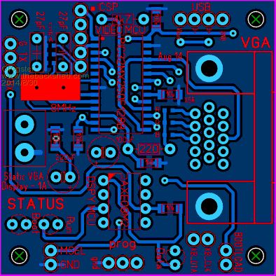
BOTTOM COPPER: 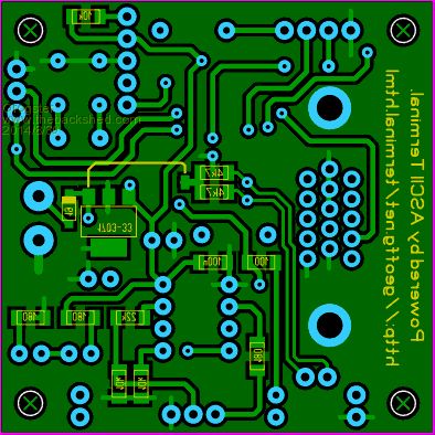
Prompted by Mick's example, I have managed to squeeze in the two pull-up resistors on the keyboard lines. I had to have a single wire link on the bottom of the board - could not find a way to get the track back to the input connector without hitting another track somewhere!
I also added a Schottky diode on the bottom, as reverse polarity protection on the input voltage.(this required moving the 100n cap from the bottom, to the top layer) Smoke makes things work. When the smoke gets out, it stops! |
||||
bigmik Guru Joined: 20/06/2011 Location: AustraliaPosts: 2870 |
Hi Grogster, I cant do a photoshop mockup as i am interstate and only have an iPad with me.. But, can you not squash the two tracks above the Vreg a wee bit, the top track of the two can go closer to the crystal, the gap between them have a double up of the clearance and can be closed to the standard gap, The Vreg can be pushed down slightly.. That will enable 5v track from vreg to go to the left of the vertical track 3v3 the two resistors may then straddle the 3v3 track instead of your gnd pour, Mick Mick's uMite Stuff can be found >>> HERE (Kindly hosted by Dontronics) <<< |
||||
| Grogster Admin Group Joined: 31/12/2012 Location: New ZealandPosts: 9066 |
Nice spotting - will make those changes later today. Thanks.  Smoke makes things work. When the smoke gets out, it stops! |
||||
| Grogster Admin Group Joined: 31/12/2012 Location: New ZealandPosts: 9066 |
OK, here is the new bottom copper layer: 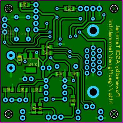
I think we have everything in there now! Smoke makes things work. When the smoke gets out, it stops! |
||||
| bigmik Guru Joined: 20/06/2011 Location: AustraliaPosts: 2870 |
Grog, Looks good now.. Mick Mick's uMite Stuff can be found >>> HERE (Kindly hosted by Dontronics) <<< |
||||
