Notice. New forum software under development. It's going to miss a few functions and look a bit ugly for a while, but I'm working on it full time now as the old forum was too unstable. Couple days, all good. If you notice any issues, please contact me.
viscomjim Guru Joined: 08/01/2014 Location: United StatesPosts: 925
Posted: 03:24am 09 Oct 2014
Copy link to clipboard
Print this post
Hey Jman and all, this is great, can't wait to get my fram on. Bonus RTC. Hopefully Zonker will have his awesome 28 pin SuperDuperMicroMite soon... or FraMicroMite...Edited by viscomjim 2014-10-10
centrex Guru Joined: 13/11/2011 Location: AustraliaPosts: 320
Posted: 09:21am 09 Oct 2014
Copy link to clipboard
Print this post
Thanks Grogster
Yes date and time stamping would be desirable, my fram does not have an rtc built in but I do have an rtc attached to the micromite which updates the micromite every 12 hours.
Is there any reason to use binary for the I2C address in lieu of the more normal hex.
CliffCliff
Grogster Admin Group Joined: 31/12/2012 Location: New ZealandPosts: 9593
Posted: 11:57am 09 Oct 2014
Copy link to clipboard
Print this post
I will write a sub that includes the MMBASIC date and time, and this will be written to the FRAM along with the data you want.
Does not matter what kind of RTC, as the sub will make use of DATE$ and TIME$, which can be set by any RTC you may have connected.
On the binary address - no, you can use hex or decimal - whatever.
It's just for I2C, I find that binary notation is easier - FOR ME.
But if you find hex simpler, then by all means......
It is just a personal choice.
I just find it easier to visualize the address in binary over hex.
In my experiments, I am using 1010000 for the address, which is 50h, so you could use &H50 in place of the binary for the address, and it would mean the same thing.Edited by Grogster 2014-10-10Smoke makes things work. When the smoke gets out, it stops!
Grogster Admin Group Joined: 31/12/2012 Location: New ZealandPosts: 9593
Posted: 02:19pm 09 Oct 2014
Copy link to clipboard
Print this post
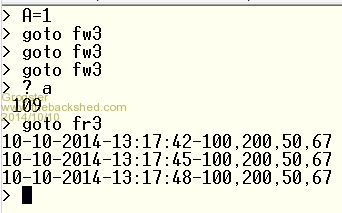
Cliff - this SHOULD do what you want, but it does depend somewhat, on how you want the data formatted......
You have to have set the RTC before calling FRAM, or the date and time stamp will be wrong.
WRITER: (fw3 in my example shot below)
[code]
V1=100:V2=200:I1=50:I2=67
FRAM (V1,V2,I1,I2)
[/code]
READER: (fr3 in my example shot below)
[code]
I2C open 400,100
I2C write &B1010000,0,2,0,1 'Set the reading start address
D1$=""
Do
I2C read &B1010000,1,1,B
D1$=D1$+Chr$(B)
If Len(D1$)>100 Then D1$="":Exit Do
If B=13 Then Print D1$:D1$=""
Loop
[/code]
ERASER:
[code]
KILL:
I2C open 400,100
Input "Start address: "; A1
Input "End address: ";A2
For X=A1 To A2
I2C write &B1010000,0,3,X\256,X Mod 256,0
Next
I2C Close
End
[/code]
SUBROUTINE:
[code]
Sub FRAM (V1V,V2V,I1I,I2I)
I2C open 400,100
DA$=Chr$(A\256) + Chr$(A Mod 256) + Date$ + Chr$(45) + Time$ + Chr$(45)
DB$=Str$(V1V) + Chr$(44) + Str$(V2V) + Chr$(44)
DC$=Str$(I1I) + Chr$(44) + Str$(I2I)
D$=DA$ + DB$ + DC$ + Chr$(13)
I2C open 400,100
I2C write &B1010000,0,Len(D$),D$
I2C Close
A=A+Len(D$)
End Sub
[/code]
Edited by Grogster 2014-10-11Smoke makes things work. When the smoke gets out, it stops!
jman Guru Joined: 12/06/2011 Location: New ZealandPosts: 711
The above will output a 512HZ square wave on pin 5
The below will set the RTC back to normal
I2caddr = &h68 ' FM31256 I2C address
I2C open 400,100 ' Enable I2C
I2C write I2caddr, 0, 2, &H00 ,&B00 ' Back to normal
I2C Close
On my test setup the output was 512hz measured with my frequency counter
If I measure if with the Micromite it measures 510hz
Try code below with pin 5 of the Fram connected to pin 15 of the micromite
Setpin 15 ,FIN ,500
Pause 600
Print Pin(15)
To set the calibration you will need a really good frequency counter to measure the error amount then look up the error on page 11 and 12 of the datasheet
Once you have the error this can be written to the Fram with
jman Guru Joined: 12/06/2011 Location: New ZealandPosts: 711
Posted: 08:29pm 09 Oct 2014
Copy link to clipboard
Print this post
Hi Cliff
I have been giving this some thought.
What would the maximum of your readings be ?
Regards
Jman
centrex Guru Joined: 13/11/2011 Location: AustraliaPosts: 320
Posted: 09:55pm 09 Oct 2014
Copy link to clipboard
Print this post
Hi Jman
I am just about to try out Grogsters bit of code which no doubt increase my knowledge of I2C and Fram no end.
But to answer your question it would be a 12volt nominal solar powered system,
so the voltages would be from about 10.5 to about 18 the current in the vicinity of 2 to 10 amps.
The whole idea was to get my head around using the Fram for any sort of data logging using the MicroMite in particular BigMicks MuP.
Thanks for your interest.
CliffCliff
centrex Guru Joined: 13/11/2011 Location: AustraliaPosts: 320
Posted: 11:20pm 09 Oct 2014
Copy link to clipboard
Print this post
Grogster
It all does what you say it should do except I only get one reading not three as your demo shows.
Not to worry it gives me plenty to study and come to grips with.
It probably helps a number of others to see how it is all done.
Many thanks
CliffCliff
Grogster Admin Group Joined: 31/12/2012 Location: New ZealandPosts: 9593
Posted: 01:46pm 10 Oct 2014
Copy link to clipboard
Print this post
Hi Cliff - the sub expects you to send it four values for writing to the FRAM. V1(voltage one), V2(voltage 2), I1(current one) and I2(current two).
Did you copy all my code examples exactly, or did you change them to suit yourself?
If you tried an exact copy, then it should work exactly as shown. If you changed the code for your purposes, please post that code, so I and others can find why it is now only saving one value.
Also worth noting, is that you may need to erase the FRAM in the area that you are writing to, if it has been written to before, as this can confuse the results - that happened to me, hence the KILL routine....Smoke makes things work. When the smoke gets out, it stops!
centrex Guru Joined: 13/11/2011 Location: AustraliaPosts: 320
Posted: 02:19pm 10 Oct 2014
Copy link to clipboard
Print this post
Hi Grogster
All is working fine, the KILL routine gets rid of the junk which did confuse for awhile.
I have it running recording the input to pin 2 and dummy variables for the others every 5 minutes via the settick interupt.
Now that it is all running it is easy to play with various options like only recording the time and date into the first location etc.
I havent got my head around how the memory location is determined I can see the maths but how does the I2C send this to the FRAM from the string that is generated.
Many thanks
Cliff
Cliff
Grogster Admin Group Joined: 31/12/2012 Location: New ZealandPosts: 9593
Posted: 02:56pm 10 Oct 2014
Copy link to clipboard
Print this post
The FRAM expects the first two bytes sent to it, to be the address bytes, and any other bytes after that are data bytes.
This was something that confused me a bit too for a start - jman and others helped me get my head around that, and once I understood that, reading and writing was easy-peasy.
The "A\256" and "A Mod 256" were bits of code supplied to me by other members here, in order to work out the two-byte address.
As mentioned above, this particular FRAM uses word addressing, so you have to send two 8-bit bytes to the FRAM, to tell it where you want to start writing or reading from.
We use "A\256" to find the MSB(most significant byte), and "A Mod 256" to find the LSB(least significant byte).
Now we have those values, we insert them as the first two bytes of the data string to be sent to the FRAM. So, "D$=chr$(A\256) + chr$(A Mod 256)" - this takes the two address bytes, and makes them the first two bytes of the data string, then we just add the wanted data to the end of this same string, and once the string is built up the way we want, we just send the whole thing to the FRAM.
Smoke makes things work. When the smoke gets out, it stops!
centrex Guru Joined: 13/11/2011 Location: AustraliaPosts: 320
Posted: 03:17pm 10 Oct 2014
Copy link to clipboard
Print this post
As you say easy-peasy once you have it explained, my particular fram is MB85RC256V from Adafruit their service was excellant only took a couple of weeks to get to Aus.
Playing with electronics is a bit remote from the daytime job of servicing sailplanes.
CliffCliff
centrex Guru Joined: 13/11/2011 Location: AustraliaPosts: 320
Posted: 07:00pm 01 Nov 2014
Copy link to clipboard
Print this post
Hi all
Anyone wanting to read or write to FRAM chips the twofingers modified code posted earlier does it easily.
My FRAM is an Adafruit MB85RC256V 32KB device.
CliffCliff
Zonker Guru Joined: 18/08/2012 Location: United StatesPosts: 767
Posted: 05:50pm 17 Nov 2014
Copy link to clipboard
Print this post
@Grogster...
I am working with your Fram write routine and noticed that after you write the data record to memory the address of the next record is off by 2 because you have included the Fram address bytes into the address count... simple to fix but was causing 2 byte 00's holes in fram memory... I changed the code a bit to just write 2 voltages read from pins 2 and 3 connected to some pots so I can change the input voltages... Aso changed the Fram read routine to keep reading until it bumps into a value of 0 indicating the next open address to write to...
Sub ReadVals
SetPin 2, AIN
SetPin 3, AIN
Print "Pin 2 = "; Pin(2)
Print "Pin 3 = "; Pin(3)
writeFRAM (Pin(2), Pin(3))
End Sub
Sub readFRAM
Print "Fram address = ";A
I2C open 400,100
I2C write &B1010000,0,2,A\256,A Mod 256 'Set the reading start address
D1$=""
Do
I2C read &B1010000,1,1,B
D1$=D1$+Chr$(B): A=A+1
If B=0 Then D1$="":Exit Do
If B=13 Then Print D1$:D1$=""
Loop
A=A-1' subtract 1 for decticting the B=0
Print "Fram address = ";A
End Sub
Sub KILL
I2C open 400,100
Input "Start address: "; A1
Input "End address: ";A2
For X=A1 To A2
I2C write &B1010000,0,3,X\256,X Mod 256,0
Next
I2C Close
End Sub
Sub writeFRAM (V1V,V2V)
I2C open 400,100
DA$=Chr$(A\256) + Chr$(A Mod 256) + Date$ + " " + Time$ + " "
DB$=Str$(V1V) + " " + Str$(V2V)
D$=DA$ + DB$ + Chr$(13)
I2C open 400,100
I2C write &B1010000,0,Len(D$),D$
I2C Close
A=A+Len(D$)-2
End Sub
Grogster Admin Group Joined: 31/12/2012 Location: New ZealandPosts: 9593
Posted: 05:59pm 17 Nov 2014
Copy link to clipboard
Print this post
Thanks for the heads-up.
Yes, that is well spotted, my man, well done.
It would be giving you those two zero-byte addresses too, because, as you say - I am inserting the address bytes as part of the string sent to the FRAM, so yep - there would be a two byte "Gap" there.Smoke makes things work. When the smoke gets out, it stops!