
|
|
Forum Index : Microcontroller and PC projects : Hardware Debounce for Micromite?
| Page 1 of 2 |
|||||
| Author | Message | ||||
Oldbitcollector Senior Member Joined: 16/05/2014 Location: United StatesPosts: 172 |
I'm a little surprised that I didn't see a reference to this in the Micromite manual. Is there a recommended switch circuit that includes hardware level debounce? (See attached) Thanks Jeff 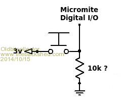
My Propeller/Micromite mini-computer project. |
||||
| hitsware Guru Joined: 23/11/2012 Location: United StatesPosts: 535 |
See page 15 ..... Adjust capacitance value for purpose .... I.E. short delay = debounce |
||||
| viscomjim Guru Joined: 08/01/2014 Location: United StatesPosts: 925 |
I have used this with no problems, works weil with uMite... R1 = 10k C1 = .01uf or .1uf 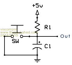
|
||||
| atmega8 Guru Joined: 19/11/2013 Location: GermanyPosts: 738 |
sorry, but how should this work? The c1 is her only important for generating some sparks and demaging the switch;-) What is your config on the pin Interrupt? |
||||
| viscomjim Guru Joined: 08/01/2014 Location: United StatesPosts: 925 |
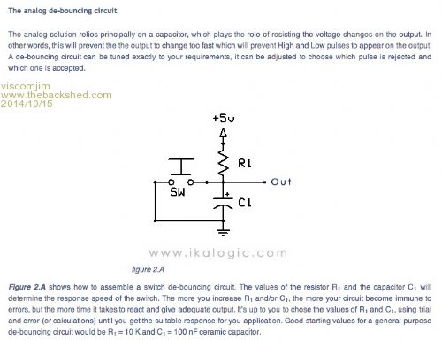
I typically do SETPIN XX, INTL, SWITCHINT. XX being the pin number and SWITCHINT being the interrupt routine I want to execute. Here is some info from this forum. |
||||
| atmega8 Guru Joined: 19/11/2013 Location: GermanyPosts: 738 |
Ok, my answer was a little bit to fast...... After thinking some minutes about it i agree that this can do a good debounce job;-) I will Test this .. THX |
||||
| hitsware Guru Joined: 23/11/2012 Location: United StatesPosts: 535 |
Not altogether .... But for practical purposes ? |
||||
| viscomjim Guru Joined: 08/01/2014 Location: United StatesPosts: 925 |
Hi Atmega8, I also use this setup on both sides of a rotary encoder using the built-in function on the uMite and it really cleans things up easily. Nice smooth increments (or decrements). |
||||
| atmega8 Guru Joined: 19/11/2013 Location: GermanyPosts: 738 |
Alps Encoder Hardware Debouncing Hi Jim, however, it is a litte bit strange for me to shortcut a capacitor. But if it works, why not ;-) In the above link, you can see ALPS recommendation for their Rotary Encoders. There is just a serial resistor making an e function instead of a shortcut. This is mathematical correct and more electro engineering practise. +++++++++++++++++++++++++++++++++++++++++ With enough thrust, even pigs can fly ;.) |
||||
| robert.rozee Guru Joined: 31/12/2012 Location: New ZealandPosts: 2528 |
someone earlier posted a link to a page containing this circuit: 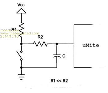
it addresses your concern about shorting out the capacitor (in theory a quite valid concern), and provided R1 is much less than R2 then ramp up and ramp down times will be fairly similar. the micromite digital inputs almost certainly go through schmitt triggers, so this circuit will work well. t = 0.7 x R x C (approximately) for t = 1mS, reasonable values would be R1 = 1k5, R2 = 15k, and C = 0.1uF. while the button is held pressed about 2mA will flow if R1 = 1k5. rob :-) |
||||
| paceman Guru Joined: 07/10/2011 Location: AustraliaPosts: 1329 |
Reading through the whole 26 page text of the link that Gizmo posted earlier: http://www.eng.utah.edu/~cs5780/debouncing.pdf "A guide to De-bouncing" that looks right-on Rob. Greg |
||||
| viscomjim Guru Joined: 08/01/2014 Location: United StatesPosts: 925 |
I am now curious to see which one actually works? I personally have been using the one I described earlier in the thread, and it has worked for many a project, but now it seems that I was doing it incorrectly (sparks and stuff). Can someone verify which method is the one we should all agree on? We should all have a debounce contest and the winners solution is the one every one uses from now on. It's like a big guessing game. Which one actually works????? It seems like this is proprietary information. The original question was... What, for Christ's sake, if not OBC's sake, is the answer????? |
||||
| hitsware Guru Joined: 23/11/2012 Location: United StatesPosts: 535 |
Who's " OBC " ... ? |
||||
| viscomjim Guru Joined: 08/01/2014 Location: United StatesPosts: 925 |
Hi Hitsware, OBC is the one who started this thread and the mastermind behind the MicroMiteCompanion (MMC) aka BadAssModernDayRetroComputer, or as I like to call it... BAMDRC. He is a virtual genius when it comes to the propeller chip. Take a look at his forum, www.propellerpowered.com and you will understand. He magically combined the uMite and the propeller and made virtual retro computing history (or as I, and many others, like to call it, VRCH). Take a look here, and here. And here. I may have lacked focus on your question. OBC stands for OldBitCollector aka Jeff. Not to be confused with ODB, as referenced here. But if I were a betting man, ODB had no clue what a propeller was. Whaaaaaattttt.... |
||||
| hitsware Guru Joined: 23/11/2012 Location: United StatesPosts: 535 |
> What, for Christ's sake, > if not OBC's sake, > is the answer????? Perhaps it needs to be done to 'taste' Like stuffing speaker cabinets ... Which is,in fact, also 'dampening' I'd start with the capacitor until I burned a switch or blew a pin .... @ OBC ... Sorry I had forgot your acronym  |
||||
| Oldbitcollector Senior Member Joined: 16/05/2014 Location: United StatesPosts: 172 |
Actually, I've been bit amused that a "standard answer" wasn't very quickly forthcoming. This seems like a "101" type question. I've been lurking this thread hoping that a consensus would be reached. I've already started testing some variations to see what seems to work the best. Perhaps this is something that Geoff might add to his next revision of the Micromite Manual with a an officially "recommended" circuit. It seems that reading a switch is something that could be contained in the section right after lighting an LED. In the meantime, keep slugging it out. I'm making notes and popcorn. :) My Propeller/Micromite mini-computer project. |
||||
TassyJim Guru Joined: 07/08/2011 Location: AustraliaPosts: 6538 |
There are so many different switches, all with different switching characteristics that there is no simple answer. I have often used the simpler one resistor and one capacitor. 4.7k and 0.01uF would be typical. The circuit with the second resistor would reduce any overshoot and ringing when the capacitor is shorted and is the better choice. It also has the advantage of protecting the micro's input from long leads connected directly to pins (not a good thing). Most of the inputs on the PIC32's have Schmitt trigger so the slow rise times don't cause any grief when at mid voltage. I still use software debounce when it is important. Jim VK7JH MMedit |
||||
| MicroBlocks Guru Joined: 12/05/2012 Location: ThailandPosts: 2209 |
My entry to the "competition": 
[Modified picture from Rob] 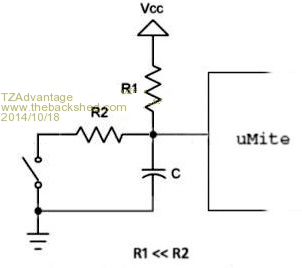
!Note R1 = 4 x R2. While the switch is closed it draws less power as both resistors are in series. The two resistors are a basic voltage divider when the switch is closed, so it works even with an analog input. 
Because it being a voltage divider R2 needs to be small enough to get a 'low' on the input pin. My estimate is that R1 has to be about 4-5 times higher in resistance then R2. In battery operated systems that have switches that can be closed for a long time it will give some more live. Microblocks. Build with logic. |
||||
| robert.rozee Guru Joined: 31/12/2012 Location: New ZealandPosts: 2528 |
under most circumstances, they both probably will perform equally well. with the switch shorting the capacitor directly there will be a very small arc if the contacts bounce, which will serve to maintain the short throughout. but this arc will be so small as to do no real damage to a switch actuated by a person. however... some years ago i set up an experiment to monitor startup durability of a power supply design. startup was normally initiated by a conductive-rubber push button being pressed by the operator, but for the purposes of the experiment this was replaced by a rather large relay driven by a timer that fired briefly every 10 seconds. the output of the power supply was connected to an electro-mechanical counter. because the power supply had no 'heartbeat' signal being sent back to it (from the rest of the product), by design it would shut down automatically after a few seconds. the end result was that every 10 seconds the power supply would be turned on, which would then increment the counter. after a few seconds it would turn off. the power supply itself was sitting in a thermal oven, that over a period of several hours would cycle between a high of 85 degrees C and a low of -10 degrees C. every day i would check the counter was still going up and that nothing had exploded. to my complete bewilderment, after about 8 months (heading up towards 2 million cycles) the setup stopped working. i traced the failure to the (20A) relay contacts connected in place of the power switch, which were massively eroded. the relay had 3 sets of contacts, with only the one set being damaged. the conclusion - root cause analysis: the tiny capacitor in the switch debouncing circuit (just a single resistor and a capacitor) had very very slowly eaten away the relay contacts through the around 2 million tiny arcs the experiment had created. the moral of the story: if you expect your switch contacts to be closed several million times over the life of your project, it would be prudent to use a second resistor. but, in practice, this is only likely to be an issue if some sort of machine is actuating the switch repeatedly. rob :-) |
||||
| paceman Guru Joined: 07/10/2011 Location: AustraliaPosts: 1329 |
Another 2 cents worth. Having read the above link again I'd qualify my "right-on" comment to, right circuit but resistances too low. Pages 12 to 16 of this link discusses this circuit and he gives some pretty valid reasons to include R2. He recorded digital scope traces from 18 different types of switches (photos on page 2) and each switch was opened and closed 300 times to get a good sampling. Page 4 shows average de-bouncing times for opening and closing for each switch type and the times are surprisingly long in some cases. Most were somewhere under 10 mS but quite a few were 20 to 50 mS - one particularly bad one was 150 mS. He shows some example calcs using 20 mS as the time constant because of the results of the above tests. Using a 0.1uF cap and 5v, it gave 180K for R2 and 18K for a 1uF cap. He considered 0.1 uF to be a bit low (reasons given) but for the PIC32's maybe it's OK. (He did this work in 2004 and noted that "most microprocessors don't have a schmitt trigger input". Because of that he suggested a CMOS 74AHCT14 hex inverter as the schmitt trigger input - but we don't need to do that.) TZ's point about being able to use his circuit also as a voltage divider has merit but the point about drawing less current because of R1 & R2 both in series with the switch closed seems less useful - if R2 is a lot lower value why not just lift R1 a bit. Issues around maintaining the logic 'low' in that circuit is something for you proper electronic guys to ponder 
Greg |
||||
| Page 1 of 2 |
|||||
| The Back Shed's forum code is written, and hosted, in Australia. | © JAQ Software 2026 |
