
|
|
Forum Index : Microcontroller and PC projects : Waking up the uM.....
| Page 1 of 2 |
|||||
| Author | Message | ||||
Grogster Admin Group Joined: 31/12/2012 Location: New ZealandPosts: 9975 |
Hi folks. 
I am playing around with the WAKEUP and sleep ideas on the uM tonight, but am unable to make them work. First off, I wrote a basic code to simply flash the good-ole LED on and off, interrupted by sleep times: [code] ST: CPU 5 Do SetPin(23),DOUT SetPin(43),DOUT 'Charge up cap on wakeup pin Pin(23)=1 Pause 1000 Pin(23)=0 CPU sleep Loop [/code] This is a 44-pin uM module. I have tried various value caps across pin 43 and ground, but the uM never ever wakes up. Can someone indicate to me what I am doing wrong? Manual says on page 13 about connecting cap to wakeup pin and ground. No mention at all is mentioned as to a reference capacitance, so I started with 1uF and worked down from there. Even at 100n, the uM stays asleep forever, so either I am not doing something right(most likely), or there is some other problem with use of the wakeup pin. EDIT: Crikey - you don't need much capacitance!!!! 
Getting a result now with a 330pF ceramic. This gives about a 12-second sleep time. EDIT: 100pF ceramic gives about 4-5 second sleep time. All seems to be working, so most of you can ignore this thread. But then - you've already read to this point, haven't you, so i'm afraid I have just wasted a few minutes of your life.  Smoke makes things work. When the smoke gets out, it stops! |
||||
| Geoffg Guru Joined: 06/06/2011 Location: AustraliaPosts: 3362 |
(I read it also...) Unfortunately the capacitor method is unreliable so the next version for the MX170 (which I am working on now) will have a method of specifying a sleep time without requiring any external components. Geoff Geoff Graham - http://geoffg.net |
||||
| Grogster Admin Group Joined: 31/12/2012 Location: New ZealandPosts: 9975 |
Hi Geoff Can you elaborate a little more on the unreliability of the capacitor method? Seems to be working great, now that I have settled on a 1nF cap, which gives me about 35 second sleep time....
I don't need to-the-second accuracy, just some form of sleep time I can set that is about 30 seconds or so, which the 1nF seems to be doing, but I am now curious about the unreliability you speak of.... Smoke makes things work. When the smoke gets out, it stops! |
||||
| robert.rozee Guru Joined: 31/12/2012 Location: New ZealandPosts: 2528 |
hi, i believe your code should be something like this: ST:
CPU 5 Do Pin(43)=1 SetPin(43),DOUT 'Charge up cap on wakeup pin Pause 1000 CPU sleep 'Reconfigure pin 43 as input and sleep Loop in the above [untested] snippet, pin 43 is configured as an output pulled high - this will start charging the capacitor. the "CPU sleep" command itself will configure pin 43 as an input (high impedance) and wait for the pin to change state (1 -> 0). the problem with just a capacitor is that the impedance of a pin when configured as an input is so high that operation is unpredictable. the time will be affected by humidity, fingerprints on the PCB, and manufacturing variances in the pic32 and capacitor itself. any leakage to Vcc will ensure that the capacitor never discharges. to eliminate this, use a resistor in parallel with the capacitor, where the time to wakeup will then be something like: sleep time = 0.7 x Rt x Ct if you use a 150k timing resistor and want a 1 second sleep time, Ct will be about 10uF. going as high as 1M5 for the resistor should be fine, as will going down to 0.005uF for the capacitor. when using an electrolytic, bear in mind that the tolerance may be as wide as -50%/+100% and that the value will change as the component ages. the upper limit of the timing resistor is to remain much less than the leakage current on the wakeup pin, while the lower limit of the capacitor is to keep well above possible stray capacitances. to avoid current spikes appearing on Vcc, you may also want to (optionally) add a 1k resistor in series with the wakeup pin - this will limit inrush current when charging the timing capacitor. just make sure that the series resistor value is 1/10th or less of the timing resistor, and that your 'awake' time is long enough to fully charge up the capacitor. cheers, rob :-) |
||||
| Geoffg Guru Joined: 06/06/2011 Location: AustraliaPosts: 3362 |
Grogs, Robert has explained the issues well. The timing varied depending on temperature, etc. Geoff Geoff Graham - http://geoffg.net |
||||
TassyJim Guru Joined: 07/08/2011 Location: AustraliaPosts: 6538 |
Capacitor values vary a lot and they all tend to have leakage which is the main culprit when you are trying to charge them through a high value resistor. It is very easy to end up with a capacitor which never charges sufficiently to trigger the wakeup. Relying on the internal resistance to self discharge is also very hit and miss. For accurate wakeup's, use the PCF8563 RTC (or similar) For not so accurate, a 555 works well and the CMOS version is very low power. For the MX170, wait for Geoff's next update. Jim VK7JH MMedit |
||||
| Grogster Admin Group Joined: 31/12/2012 Location: New ZealandPosts: 9975 |
Thanks folks, and especially Rob for his excellent description. This does jive with my attempts to manually wake the uM once asleep via the cap - 50/50 on if I can manually wake it, sometimes needing a ground reference, sometimes needing a Vcc reference - tricky. I will investigate the 7555 idea as a low-power timer that could wake the uM. Geoff: With the new 170 you are working on, if you have something along the lines of CPU SLEEP 5000 for a 5s sleep kind of thing, will you still be able to interrupt that with the wakeup pin? Smoke makes things work. When the smoke gets out, it stops! |
||||
| Grogster Admin Group Joined: 31/12/2012 Location: New ZealandPosts: 9975 |
OK folks, I have built a test 7555 circuit, which seems to be working well. 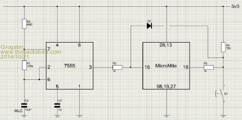
The 7555 operates as an astable with R1, R2 and C2 setting a time period of about 35 seconds. R3 provides some current-limit protection to the MicroMite, and D1 prevents the 7555 from tripping the MicroMite via S1 during it's timing cycles. The MicroMite is woken every timer cycle, where it checks the condition of the battery, then goes back to sleep. The idea behind all this, is to maximize battery life, by not allowing the CPU to run all the time, sucking juice from the battery, while doing nothing but waiting for a button press. If S1 is pushed during a sleep cycle, D1 pulls the WAKEUP pin low and wakes the MicroMite allowing it to process the button press. During S1 presses while the MicroMite is awake, the 7555 is still running in the background, but as the MicroMite is now awake, it just ignores the 7555 output till the MicroMite is put back to sleep again. Can anyone see anything obviously wrong with this setup or suggest a better idea? Smoke makes things work. When the smoke gets out, it stops! |
||||
crez Senior Member Joined: 24/10/2012 Location: AustraliaPosts: 153 |
A while back I posted a bit of code which had the pcf8563 real time clock chip wake the micromite at a pre-programmed time of day or after a set number of minutes or seconds. Most folks won't have the RTC connected though. David |
||||
| Grogster Admin Group Joined: 31/12/2012 Location: New ZealandPosts: 9975 |
Yeah, Jim hinted above about using an RTC to wake the module, but I don't have an RTC on the design - no need for it. Smoke makes things work. When the smoke gets out, it stops! |
||||
| robert.rozee Guru Joined: 31/12/2012 Location: New ZealandPosts: 2528 |
i'd be interested to know how you got along with just a resistor and capacitor in parallel. rob :-) |
||||
| Grogster Admin Group Joined: 31/12/2012 Location: New ZealandPosts: 9975 |
I never got around to trying the resistor and cap in parallel, as it seemed that at best, this would still be drifty over time etc. For the sake of experimentation, I will hook that up now and post back. Smoke makes things work. When the smoke gets out, it stops! |
||||
| MicroBlocks Guru Joined: 12/05/2012 Location: ThailandPosts: 2209 |
I think using the resistor and cap would be good enough for now. Once Geoff has it added to the firmware the problem is basically solved without external hardware. When you are in the process of designing and possibly even a pcb made then waiting for that feature is worthwhile. If a pcb is made then all you have to do to use that new feature is to leave out the cap and resistor. A 555 seems to much for this, as it also consumes power and wastes pcb space. Microblocks. Build with logic. |
||||
| Grogster Admin Group Joined: 31/12/2012 Location: New ZealandPosts: 9975 |
OK, I have made the changes, and have a cap and resistor in parallel. For testing, I am using 330pF and 1M5 in parallel. Code runs into first CPU sleep command, then never wakes up. Cap and resistor from pin 43 to ground. Pin(43)=1 at start of loop to charge up the cap. EDIT: OK, got the uM cycling again, but I had to remove the resistor in parallel with the cap. With the resistor in place, the uM never wakes up. Any further suggestions? Smoke makes things work. When the smoke gets out, it stops! |
||||
| robert.rozee Guru Joined: 31/12/2012 Location: New ZealandPosts: 2528 |
that would be because: sleep time = 0.7 x Rt x Ct Rt = 1,500,000 ohm Ct = 330 x 10^-12 = 0.00000000033 farad => 0.7 x Rt x Ct = 350uS i'm suspecting that with those values the capacitor will have discharged before the processor has had time to nod off. now try 10uF and 150k. this will give 1 second. 10uF and 1M5 will give 10 seconds. 33uF and 1M5 will give about 35 seconds. rob :-) |
||||
| Grogster Admin Group Joined: 31/12/2012 Location: New ZealandPosts: 9975 |
Thank you, Rob, for your suggestions and technical explanations. I will try those values, and post back.
EDIT: Sorry to have to report, that with 10uF and 1M5 or 1uF and 1M5, uM will not wake up. Smoke makes things work. When the smoke gets out, it stops! |
||||
| robert.rozee Guru Joined: 31/12/2012 Location: New ZealandPosts: 2528 |
most odd. i've just tested the following code with a 10uF capacitor and 220k resistor in parallel from pin 16 to ground on a 28-pin micromite: CPU 5
Do Pin(16) = 1 SetPin(16), DOUT ' Charge up cap on wakeup pin Print "awake" Pause 1000 Print "asleep" CPU sleep ' Reconfigure pin 16 as input and sleep Loop it works perfectly for me, awake for 1 second, and asleep for a couple of seconds in a continuous loop. are you sure you are using the correct pin for wakeup? you should be able to see the voltage go up with a multimeter, then slowly decay over a couple of seconds. rob :-) |
||||
| Grogster Admin Group Joined: 31/12/2012 Location: New ZealandPosts: 9975 |
OK, with your 220k and 10uF, I can get the same results as you. I guess 1M5 was too high a value? Would I be correct in my assumption that lower value caps with high-value resistors is the preferable arrangement over large value caps and lower value resistors? I will play around with this idea more. EDIT: OK, with 10uF tantalum and 4M7 resistor, I am getting about 45 seconds sleep time. If I went down this road, I would be using an X5R 10uF MLC capacitor - the same cap I use for the uM Vcap. Being X5R, it should be reasonably stable over time and temperature. EDIT: OK, I seem to have found out that under certain circumstances, the uM seems to just stay asleep forever. When I try to use my button to wake the uM, it does not wake, then it NEVER wakes. Example: Apply power, run code. uM starts sleeping and waking as it should. While asleep, try to wake it with the button across the wakeup pin and ground, uM does not wake, and then the uM NEVER wakes no matter how long you wait. To get it back, I have to cycle power or press the RESET button(I'm using a WW 44-pin module) This does not happen with the 7555 driver circuit. Witht the 7555, the uM sleeps and wakes on command, and also can be woken any time with the button. Something about the cap + reistor idea which does not want to work in a reliable sence, as was initially pointed out by Geoff. EDIT: Ahhhhh - forgot the 1k series resistor between the WAKEUP pin, and the switch to ground. I can wake the uM on button press now. EDIT: OK, here we have the circuit as it stands now, and this seems to be working fine, including waking on command when S1 is pressed. 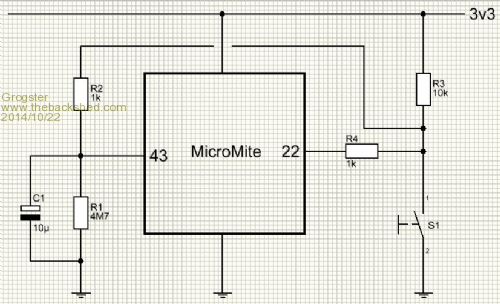
Smoke makes things work. When the smoke gets out, it stops! |
||||
| robert.rozee Guru Joined: 31/12/2012 Location: New ZealandPosts: 2528 |
i tried it with a 3M3 resistor, and it appeared to work - though i do feel the value could be a tad high. it all depends upon the leakage current between Vcc and the wakeup pin; the resistor needs to drain much more than the leakage current (at least 10x, preferably 100x). it is good to not have the capacitor too large, as upon each wakeup it needs to be fully charged, which is depleting your battery. i was seeing a 10uF capacitor fully charged up in less than 10mS, and did the maths to compare. the energy that has to be put into the capacitor is U = (1/2) x C x (V^2) U is in units of joules. this is the same as watt.seconds, as: P = U / t => U = P x t => P x t = (1/2) x C x (V^2) if C = 10 x 10^-6 farads, and V = 3v3, then U = 0.00011 joules, or 0.00011 watt.seconds of energy stored in the capacitor. we know that the formula for power (watts) is: P = V x I => U = V x I x t and that for a micromite pin the current is limited to something like 20mA, so: 0.00011 = 3.3 x 0.020 x t solving for t gives: t = 0.00011 / (3.3 x 0.020) => t = 1.7mS this assumes all the energy goes directly into the capacitor, which given we are using (effectively) a constant-current source to charge the capacitor is not true. the capacitor voltage ramps up linearly, with excess voltage dropped within the micromite. a fair approximation would be 50% energy efficiency, pushing out our charging time to more like 3.4mS or thereabouts. the conclusion is that with a 10uF capacitor, for each capacitor recharge you will be draining 20mA from the battery for about 4mS. or the equivalent of 80uA for 1 second; 40uA for 2 seconds, 8uA for 10 seconds, 3uA for 30 seconds. rob :-) |
||||
| robert.rozee Guru Joined: 31/12/2012 Location: New ZealandPosts: 2528 |
question: why are you using two pins? rob :-) |
||||
| Page 1 of 2 |
|||||
| The Back Shed's forum code is written, and hosted, in Australia. | © JAQ Software 2026 |
