
|
|
Forum Index : Microcontroller and PC projects : Driving LED displays....
| Page 1 of 2 |
|||||
| Author | Message | ||||
Grogster Admin Group Joined: 31/12/2012 Location: New ZealandPosts: 9975 |
Hi folks. 
I have a question concerning driving 7-segment LED displays. Quite often, you see these in projects in the likes of Silicon Chip, and on page 75 of the October issue, there is a project using four 7-segment displays. The circuit uses transistors to switch the cathode of the display. What I would like to understand, is why do they do that? It is quite common in just about any project using a couple of 7-segment displays, but I have yet to understand why the displays are hooked up like that. Why not just directly ground the cathode connection? Obviously, there is a reason, but it escapes me at the moment, so can someone here in the know enlighten me? Thanks. Smoke makes things work. When the smoke gets out, it stops! |
||||
| WhiteWizzard Guru Joined: 05/04/2013 Location: United KingdomPosts: 2991 |
Muliplexing . . . . Have the 7/8 segments going to 7/8 Output pins, then pulse the relevant transistor to apply the 7/8 outputs to the 'selected' display. So 6 digits (i.e. a clock with hh:mm:ss) would require 7 data lines and 6 'Select' lines i.e. a total of 13 I/Os. If you ground the cathode of each display you would then need six lots of 7 data lines i.e. 42 I/Os Make sense ???? 
WW |
||||
| Grogster Admin Group Joined: 31/12/2012 Location: New ZealandPosts: 9975 |
No, not really. Can you elaborate a little more please? Smoke makes things work. When the smoke gets out, it stops! |
||||
| Frank N. Furter Guru Joined: 28/05/2012 Location: GermanyPosts: 1102 |
Hi Grogster, see this picture: 
You can see the �C outputs of the controller on the left side and the switched cathode on the bottom. Frank |
||||
| Grogster Admin Group Joined: 31/12/2012 Location: New ZealandPosts: 9975 |
Ahhhhhhh - I see now.
A picture speaks a thousand words.
Would I then be correct in my assumption that the data-lines for the segments, and the cathode transistors are switching very fast - too fast for the Human eye - so it looks like a static 4-digit display, using your image? Smoke makes things work. When the smoke gets out, it stops! |
||||
OA47 Guru Joined: 11/04/2012 Location: AustraliaPosts: 1050 |
Frank, that is a very cool representation. Can I congratulate you? |
||||
| Frank N. Furter Guru Joined: 28/05/2012 Location: GermanyPosts: 1102 |
@Grogster: You are right! @Greame: Thanks a lot but I only found it on the net with Google picture search... Frank |
||||
| Grogster Admin Group Joined: 31/12/2012 Location: New ZealandPosts: 9975 |
Danke. Smoke makes things work. When the smoke gets out, it stops! |
||||
| Frank N. Furter Guru Joined: 28/05/2012 Location: GermanyPosts: 1102 |
You are welcome  |
||||
| hitsware Guru Joined: 23/11/2012 Location: United StatesPosts: 535 |
Since it takes one output pin to drive each transistor, and one for each segment, how does this lessen the pin count ? I would surmise dissapation is the reason for the transistors. |
||||
| WhiteWizzard Guru Joined: 05/04/2013 Location: United KingdomPosts: 2991 |
@hitsaware - I'll refer you back to my post: 6 digits would require 42 pins if driven directly (or 13 if multiplexed)  |
||||
bigmik Guru Joined: 20/06/2011 Location: AustraliaPosts: 2981 |
Frank, A fantastic image, shows beautifully how it all works. Grogs, Yes only one segment is actually displayed at a time but the multiplexing is done so rapidly the eye cannot see the flicker. Well that's the theory. Regards, Mick Mick's uMite Stuff can be found >>> HERE (Kindly hosted by Dontronics) <<< |
||||
| Frank N. Furter Guru Joined: 28/05/2012 Location: GermanyPosts: 1102 |
...you can often see the running segments when you look with a digital camera at a LED or a VFD display. The beat frequency composed of the muxing and the camera/LCD frequency makes it visible... Frank |
||||
| MicroBlocks Guru Joined: 12/05/2012 Location: ThailandPosts: 2209 |
There is another way but that only works for maybe 2-3 displays from MMBasic. It will probably works for more displays when a C plugin is used. This needs a warning though! If the program is not exact it can cause damage to the mcu or displays. So take care when you are going this way. Test the outputs before connecting the displays! Basically what you do is using 7 output ports, one for each segment. (8 when you also want to use a dot) The common cathode is then connected through a resistor with a output pin that will be used to select the right display. So one output pin for each display. like this: 
It works when ONLY ONE one of the 7 output pins is high and ONLY ONE of the select outputs is low. Principle of operation is to start with all output pins connected to the segments low and the output pins connected to the common cathodes of the displays high except the one you are using as the first display. Then set the output connected to the right segment high to make it light up. Then set it low again and do the next segment. When all segments that should light up are done set the selection pin high. Then repeat for the next displays. Beware!! Never light up more then one segment!! Advantage is very little extra components (1 resistor!). If you have less pins available you can use a 74HC238 to decode 3 pins to 8. This will actually prevent against programming errors as only one output pin can be active high at a time. 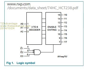
If you need more display then you can also use a 3-8 decoder like the 74HC138. This functions the same but is active low. If you use both the 74HC238 and the 74HC138 then you can have eight 7-segment display with only 6 output pins. :) As long as you can change the pins fast enough. Rmember this is not the normal way to connect 7-segment displays but can help when you not have enough pins or not enough room on the pcb. Microblocks. Build with logic. |
||||
| hitsware Guru Joined: 23/11/2012 Location: United StatesPosts: 535 |
> @hitsaware - I'll refer you back to my post: > 6 digits would require 42 pins if driven directly (or 13 if multiplexed) 6 digits would only require 42 pins if each segment (of each digit) were driven seperately. scroll down ~ 4 paragraphs .... 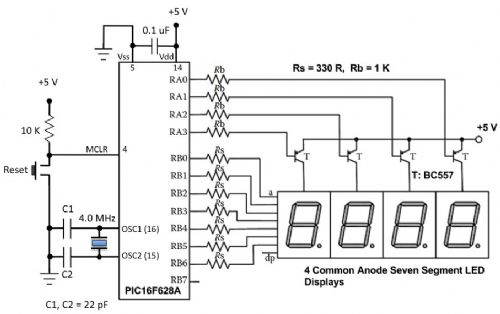
Note it would take the same number of pins if the transistors were not used. The transistors ONLY aid by relieving the pins of current delivery. |
||||
| WhiteWizzard Guru Joined: 05/04/2013 Location: United KingdomPosts: 2991 |
There seems to be some confusion in this thread. Grogster's original post asked why effectively the circuits typically use transistors to drive the cathode of each digit (as opposed to connecting the cathodes directly to ground). Taking the transistors out of the equation for now you end up with Frank's brilliant animation that he posted. Simply put, this is multiplexing each digit at a time. For this you will require 7 MPU outputs (one for each segment) and an additional number of outputs that equates to the number of digits you have. Transistors just give the ability to switch the appropriate current that the LED digits will require (if all 7 segments are on i.e. displaying the number '8', then as much as 200mA needs to flow through the cathode. This would kill a MicroMite if no transistors were used! To answer Grogster's question about 'Why not directly connect the cathodes of the digits to ground - then doing this will simply result in all digits displaying the same 'character' depending on the state of the 7 MPU outputs driving the segments. i.e. this is NOT multiplexing. If for whatever reason you wanted to ground the cathode of each digit then you would need to have an MPU output to drive each segment in all digits (so 42 outputs for 6 digits when not multiplexing, or 13 outputs when using multiplexing - as per my original post) The above is for Common Cathode displays - don't forget to 'reverse' things for Common anode displays
Another option for driving 7-segment display is to use something like a 4511 support chip. This is a bcd to 7-segment display driver and in certain situations can be beneficial requiring only four MPU outputs connected directly to the device's four BCD input pins. (@Grogs: I'm trying to write 1000 words to save having to post a picture. I'm not as 'artistic' as Frank! )
|
||||
| Grogster Admin Group Joined: 31/12/2012 Location: New ZealandPosts: 9975 |
Thanka guys, for all the extra information. I was going to ask about those 7-segment driver IC's, but WW beat me to it by mentioning one in his post above. And it's fine to have your 1000 words! It will just supplement the annimated image from page one.
I will read about the 4511 now...(I note that the circuit in the Silicon Chip article also uses one of those chips so as to only need four I/O pins to drive the 7-segment displays) Smoke makes things work. When the smoke gets out, it stops! |
||||
| Zonker Guru Joined: 18/08/2012 Location: United StatesPosts: 772 |
I have done a test like that using just direct connections to the led display and it seems to work ok... you can see brightness changes depending on how many segments are lit for each digit, but was a good basic test... ' LED Display Test Program ' Init Segment Drive Pins For x=2 To 7: Pin(x)=0: SetPin x, dout: Next x For x=9 To 10: Pin(x)=0: SetPin x, dout: Next x ' Init Digit Drive Pins For x=23 To 26: Pin(x)=1: SetPin x, oout: Next x ' Engage scan and inc routines (timer intrupts) SetTick 8, scan, 1 ' timer 1 SetTick 10, inc_digits, 2 ' timer 2 Do: Loop Sub inc_digits digit4=digit4+1 If digit4>=10 Then digit4=0: digit3=digit3+1 If digit3>=10 Then digit3=0: digit2=digit2+1 If digit2>=10 Then digit2=0: digit1=digit1+1 If digit1>=10 Then digit4=0: digit3=0: digit2=0: digit1=0 End Sub ' Subroutine to scan the 4 digit display Sub scan If scandigit>=5 Then scandigit=1 If scandigit=1 Then decode (digit1): Pin(26)=0 If scandigit=2 Then decode (digit2): Pin(25)=0 If scandigit=3 Then decode (digit3): Pin(24)=0 If scandigit=4 Then decode (digit4): Pin(23)=0 scandigit=scandigit+1 Pause 2 For x=23 To 26: Pin(x)=1: Next x ' turn off all digits End Sub Sub decode(val) If val=1 Then Port(2,6,9,2)=&B00000110 If val=2 Then Port(2,6,9,2)=&B01011011 If val=3 Then Port(2,6,9,2)=&B01001111 If val=4 Then Port(2,6,9,2)=&B01100110 If val=5 Then Port(2,6,9,2)=&B01101101 If val=6 Then Port(2,6,9,2)=&B01111101 If val=7 Then Port(2,6,9,2)=&B00000111 If val=8 Then Port(2,6,9,2)=&B01111111 If val=9 Then Port(2,6,9,2)=&B01100111 If val=0 Then Port(2,6,9,2)=&B00111111 End Sub This is just a basic up counter for the test but could be any numeric data... |
||||
| paceman Guru Joined: 07/10/2011 Location: AustraliaPosts: 1329 |
The MAX7219 is another option if you want to use the serial SPI commands to save pins. It also has the benefit of driving up to eight 7-segment LEDs. Greg |
||||
| WhiteWizzard Guru Joined: 05/04/2013 Location: United KingdomPosts: 2991 |
Good call Greg -  - I use the MAX7219 in my LED matrix clocks but now I remember about their ability to drive multi 7-segment display. The advantage they have is even segment brightness (which is controllable). - I use the MAX7219 in my LED matrix clocks but now I remember about their ability to drive multi 7-segment display. The advantage they have is even segment brightness (which is controllable).
That said however, the only thing I was shocked about was their unit price (for genuine parts). Any recommended supplier Greg . . . |
||||
| Page 1 of 2 |
|||||
| The Back Shed's forum code is written, and hosted, in Australia. | © JAQ Software 2026 |
