
|
|
Forum Index : Microcontroller and PC projects : CMM interesting issue ?
| Page 1 of 2 |
|||||
| Author | Message | ||||
| 00WReX Newbie Joined: 24/10/2014 Location: AustraliaPosts: 13 |
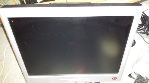
Hi All, On the way home from work last night I dropped in to Altronics and purchased a Colour Maximite kit. I had been interested in one for ages, but only just got around to getting one. Anyway, I put it together last night without any issues (I consider myself competent with a soldering iron, built many things over the years). When I first fired it up I immediately noticed a line of blue dots running horizontally through the bootup message. after performing a clear screen (CLS) the dots were still present and obviously more visible with the boot message gone. If I then press ennter so that I get to the bottom of the screen, and the screen starts to scroll up...the line of dots also scroll to the top. Hard to explain so better with a few screenshots. ALso, to note. This only happens in mode 3. If I go to mode 1, 2, 4. and type cls the dots go. If I go into the Editor (Edit) the dots go. But in mode 3 they are always there... I have tried the Maximite on three different monitors (different brands) and the dots are present on all of them The Maximite (PIC) shipped with Basic 4.4B and I upgraded to 4.5 Everything else appears to work OK, files run & save to SD, etc. Got me stumped, any thoughts would be appreciated. Cheers, Shane 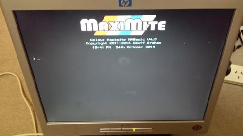
*Sorry for the poor quality, the actual colours on the screen are vibrant. But I think you at least can see what I'm talking about. |
||||
Grogster Admin Group Joined: 31/12/2012 Location: New ZealandPosts: 9979 |
Yes, that is very interesting. I have no idea why that should be, especially if that artefact goes away when you change out of mode 3 - odd. Having tried different monitors, you have ruled out a monitor-specific issue, so the problem must indeed be with the CMM - strange. Please keep us posted, if you have any luck fixing it yourself, and I will be watching this thread with interest to see what happens. EDIT: I assume that when you tried different monitors, you used different VGA leads too? If not, try a different VGA cable - it could be faulty in some way. It's a long-shot, but VGA cables can do funny things sometimes... Smoke makes things work. When the smoke gets out, it stops! |
||||
| twofingers Guru Joined: 02/06/2014 Location: GermanyPosts: 1766 |
Hi, For me it looks like a RAM issue, I would say. Perhaps damage from static electricity? Michael causality ≠ correlation ≠ coincidence |
||||
| vasi Guru Joined: 23/03/2007 Location: RomaniaPosts: 1697 |
Why are there only three colors in the graphic logo? Hobbit name: Togo Toadfoot of Frogmorton Elvish name: Mablung Miriel Beyound Arduino Lang |
||||
TassyJim Guru Joined: 07/08/2011 Location: AustraliaPosts: 6539 |
Well spotted. Check the soldering from the CPU to the VGA connector and associated components. Jim VK7JH MMedit |
||||
| MicroBlocks Guru Joined: 12/05/2012 Location: ThailandPosts: 2209 |
One of the diodes reversed or damaged? Microblocks. Build with logic. |
||||
| Grogster Admin Group Joined: 31/12/2012 Location: New ZealandPosts: 9979 |
Yes, indeed!  I'd be tracing through the RGB connections to see if there was a dry joint or reversed component, as suggested by TZA. I'd be tracing through the RGB connections to see if there was a dry joint or reversed component, as suggested by TZA.Smoke makes things work. When the smoke gets out, it stops! |
||||
| 00WReX Newbie Joined: 24/10/2014 Location: AustraliaPosts: 13 |
Hi All, Really appreciate the responses. I would love to get this sorted as it is very annoying...but I fear it could be the PIC. Sorry for the poor quality pictures, I did mention they were bad at the very bottom of my initial post 
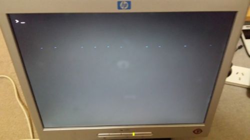
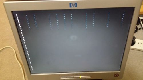
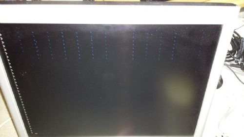
I have re-taken three more that hopefully are a little better. Other than the dots on the screen in mode 3 everything else appears exactly as I expect & also exactly like screenshots i have seen on the net. Today I had more of a play around with .mod files & copying from SD (drive B) to Flash (Drive A) and again all worked fine. All demo programs have run fine... Here are the new photo's. The dot's are not so obvious in these ones, except maybe for that last picture. 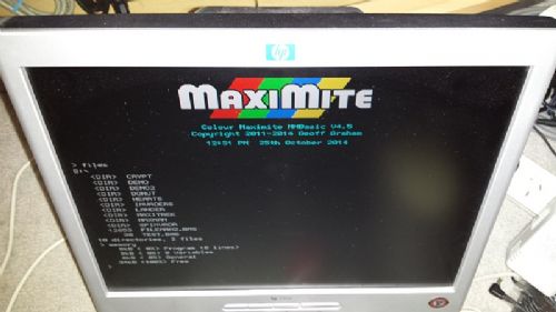
Once again, thanks for you input. Much appreciated. Cheers, Shane |
||||
| hitsware Guru Joined: 23/11/2012 Location: United StatesPosts: 535 |
I had a big video improvement when I switched monitor cables to the type with the in-line filter near the monitor end. Both the MaxiMite and DuinoMite (it seems) give off some serious emmissions. This As opposed to this |
||||
CircuitGizmos Guru Joined: 08/09/2011 Location: United StatesPosts: 1427 |
I agree with this. It appears to be RAM that is only used when in MODE 3. Micromites and Maximites! - Beginning Maximite |
||||
| twofingers Guru Joined: 02/06/2014 Location: GermanyPosts: 1766 |
@00WReX it should be quite easy to prove a RAM issue. Just use Poke (POKE keyword, offset, val) and Peek and compare. p38 MMBasic manual: You should use POKE careful: do only use "legal" (Video buffer) addresses. Any color uses 25920 bytes (mm.vres*mm.hres/8), I think. I myself have no "Color MaxiMite". Therefore please use all informations at your own risk. Michael EDIT: Alternatively you can use "SAVEBMP" (+ filename) and examine the screenshot (.BMP) with a image editing program. causality ≠ correlation ≠ coincidence |
||||
| Grogster Admin Group Joined: 31/12/2012 Location: New ZealandPosts: 9979 |
I agree with that - try a good quality VGA cable. Although, to be honest, this is probably more of a stab in the dark then anything else(as I am now thinking RAM issue too, following your better quality photos which show there are no missing colours), but it would be worthwhile trying this before getting to serious. Smoke makes things work. When the smoke gets out, it stops! |
||||
bigmik Guru Joined: 20/06/2011 Location: AustraliaPosts: 2981 |
Hi Shane, Welcome to TBS (The Back Shed), That is a very weird fault.. I cannot explain it looking at the schematic. 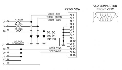
I would start by checking that the components R3, 4 & 5 are the correct value and that D4, D5, D6 are correctly oriented (There is a black bar on one end of the diodes that signifies the Cathode (the bar in the Schematic) that is connected to GND.. Use a multimeter to check that each of these Cathodes are connected to each other (means the orientation is correct). Check that there are no shorts between pins associated with the video (these are on the left of the attached schematic) and their adjacent pins.. You may need a meter to check these.. a fine scalpel may be used to scrape between the pins if they look dodgy. I would be happy to look at it for you but I gather you are in Perth if you popped into Altronics and I am in Melbourne... If you are totally stuck and will pay postage both ways I am happy to check it out for you. Regards, Mick EDIT ** the image got compressed a fair bit.. Here is the image Zipped for better clarity. Mick 2014-10-26_000739_VGA.zip Mick's uMite Stuff can be found >>> HERE (Kindly hosted by Dontronics) <<< |
||||
| 00WReX Newbie Joined: 24/10/2014 Location: AustraliaPosts: 13 |
Once again, thank you for the replies and ideas. The VGA cable I have used is different for each monitor. The HP monitor in the pictures is actually physically connected into the back of the monitor and not removable. It also has filters at both ends, just before the VGA connector and one just before it goes into the back of the computer. The other two cables used also have the filter just before the VGA connector. Thanks for the welcome bigmik, and yes, I am actually in Melbourne (Narre Warren to be precise). I purchased the CMM from the Altronics on Princes Hwy, Springvale. I have gone over the board front and back double checking everything. I have re-checked all the component values are in the correct spot including orientation...I still could have missed something, but I am fairly confident it is correct (would love to have found a component in the wrong spot or something). With the resistors I even double checked them prior to fitting with my multimeter. Not sure where you are located bigmik, but another set of eyes over it could not hurt. That would be great. Cheers for the offer. I have attached a zip with a couple of photo's of the top & bottom of my PCB. You can pretty much read all the component values. And just to show that my workmanship does not look like a total dogs breakfast  . .
Two zip files attached due to the 500kb limit. 2014-10-26_010736_20141025_111643.zip 2014-10-26_010817_20141025_112033.zip Cheers, Shane |
||||
| Grogster Admin Group Joined: 31/12/2012 Location: New ZealandPosts: 9979 |
Soldering looks fine, so no problems there that I can see. Thanks for uploading the photos - sometimes people can SAY they can solder well, but they in fact - can't, and that can be the source of the problems.  In your case, this is not an issue, and the soldering looks very nice, so ruling that out, and accidental value problems and diode problems - and having confirmed different VGA cables at this point, the only thing left really is the PIC32 chip itself and it's video RAM. In your case, this is not an issue, and the soldering looks very nice, so ruling that out, and accidental value problems and diode problems - and having confirmed different VGA cables at this point, the only thing left really is the PIC32 chip itself and it's video RAM. 
I was going to offer to send you a replacement one in exchange for your crook one so I could play with it, but Mick has beaten me to it!  Smoke makes things work. When the smoke gets out, it stops! |
||||
| bigmik Guru Joined: 20/06/2011 Location: AustraliaPosts: 2981 |
Yes, Looks a well built board Shane, I cannot see any issues that could cause your problem.. Can you try freezing (with freeze spray or an air duster can held upside down) or heating the chip to see if anything changes.. Also try pressing down on the chip. It is starting to look to me like you have a faulty chip.. Mick PS.. I live in HILLSIDE, although as I work in the horse racing inductry I will have no spare time for 2 more weeks Regards, Mick Mick's uMite Stuff can be found >>> HERE (Kindly hosted by Dontronics) <<< |
||||
| TassyJim Guru Joined: 07/08/2011 Location: AustraliaPosts: 6539 |
The fault starting of on one line then scrolling up is odd. Try typing text on a line that has the fault and see if the text overwrites the fault. Also, try changing the font. Neither will fix the problem but might help determine the cause. Jim VK7JH MMedit |
||||
| 00WReX Newbie Joined: 24/10/2014 Location: AustraliaPosts: 13 |
OK, here are three more screen shots of the 'dots', the last I promise
I think I have bored everybody enough... The first is to show that on a 'CLS' the dots appear on row 8. The second shows the dots scroll up to the top if you continuously press enter a scroll the screen, again you can see 8 rows of dots. The Third screen shows that text does not over right the dots, and in fact sit probably a couple of pixels below the normal text line. Even a full screen bitmap does not remove the dots, and depending on the background colour that the dot is in, the dot will then change to another colour. Anyway, like I said, I think I have done the dots to death...sorry guys. Thanks for all who took the time to reply. Cheers, Shane 2014-10-26_063036_MoreDots!.zip |
||||
| TassyJim Guru Joined: 07/08/2011 Location: AustraliaPosts: 6539 |
Those last photo's are good. Still no idea what the problem is unfortunately but the photos do show the position of the dots well and that might help... Jim VK7JH MMedit |
||||
| Geoffg Guru Joined: 06/06/2011 Location: AustraliaPosts: 3363 |
This is very strange and I have never seen it before. They are a pretty colour though 
I doubt very much that it is a faulty chip or RAM but you can prove it by using the SAVEBMP command to save a screen dump to a file. If that shows the dots then the chip's RAM is faulty. If not, then something is wrong outside of the chip. My guess is that it is something wrong with the earthing between the monitor and the PIC32. It would be wonderful if you have a 'scope and tried to see them on the screen. > I think I have done the dots to death... No, you have not. There is an answer somewhere and it is to our collective benefit to find what it is. Geoff Geoff Graham - http://geoffg.net |
||||
| Page 1 of 2 |
|||||
| The Back Shed's forum code is written, and hosted, in Australia. | © JAQ Software 2026 |
