
|
|
Forum Index : Microcontroller and PC projects : MX170 PCB Layout single sided
| Page 1 of 5 |
|||||
| Author | Message | ||||
| atmega8 Guru Joined: 19/11/2013 Location: GermanyPosts: 738 |
Hi, Has someone a single sided PCB Layout for a an MX170 Micromite? Thanks |
||||
| robert.rozee Guru Joined: 31/12/2012 Location: New ZealandPosts: 2534 |
i've not spotted anything, but would like to see: something the size of a credit-card, with the active i/o pins brought out to two rows of 0.2" spaced pads - one along each side (similar to arduino). with 0.2" spacing one can solder on wires, or fit screw terminal blocks. onboard 3v3 regulator, headers for serial console (no usb to serial bridge) and icsp header, reset button. power in by both 0.2" spaced pads and barrel socket. socketed dip mx150/170. optional 0.1" holes for pin headers down each side of machined-pin IC socket. supplied as a blank PCB. just my 2 cents worth, rob :-) |
||||
| paceman Guru Joined: 07/10/2011 Location: AustraliaPosts: 1329 |
Hi Dietmar, The MX170 Micromite has the same connections as the MX150 Micromite. There is no standard PCB layout for either of them because the basic form is just the programmed chip, the capacitor needed across pins 19&20 and the power/ground connections. Geoff's website MicroMite explains it and also has links to a couple of boards that have the MicroMite plus other support chips/connections incorporated on those boards - they're all double sided though. Greg |
||||
Grogster Admin Group Joined: 31/12/2012 Location: New ZealandPosts: 9980 |
I'll see what I can rustle up, Rob. 
Before I started doing double-sided, single-sided was all I would ever design, so it should be interesting to see if I can still do it without vias and the top copper. Smoke makes things work. When the smoke gets out, it stops! |
||||
| atmega8 Guru Joined: 19/11/2013 Location: GermanyPosts: 738 |
Robert, Grogster, this would be a nice PCB and very usefull. Also simple to build. I did it several times with the standard Experimenter boards with Individual round copper per hole. I think it can all be routed without any cables on the top side. Give it a try ;-) |
||||
bigmik Guru Joined: 20/06/2011 Location: AustraliaPosts: 2981 |
Hi Atmega8, Have you looked at my MuP PCB? It is 43.5mm x 49.5mm and has the following that, whilst not exactly what you asked for might suit your requirements. All Pic32 pins brought out to header pins (2 rows of 14 pins, 1 row each side of the PIC), This is at 0.1" spacing but you can get cheap screw jacks on .1" spacing that pop straight in for example These from EBay 3v3 Reg on board Headers for Serial Console (TTL Level) ICSP Header Have a read of the manual and if it is suitable please PM me or email to bigmick58@bigpond.com Regards, Mick Mick's uMite Stuff can be found >>> HERE (Kindly hosted by Dontronics) <<< |
||||
| robert.rozee Guru Joined: 31/12/2012 Location: New ZealandPosts: 2534 |
hi mick, i see you've searched ebay.com.au for the screw terminals - you'll find a far wider range for most things, and often slightly cheaper prices, if you start off your search from ebay.com (the international site). while the 0.1" terminals are nice and compact, they are considerably more expensive than the 0.2" ones, and a tad harder to work with in field environments. the PCB i have in mind affords bolting into a bit of gear and be the only PCB. in this case there is a for a degree of robustness and easy mounting that the MuP intrinsically lacks. for screw terminals, these seem to be the cheapest (per pin) choice: www.ebay.com/itm/261490358461 au$3.83 for 90 terminals, or 4.3 cents each. paceman: i see the lack of a standard layout is a bit of an advantage for the micromite. with the arduino, pin numbering is relative to the PCB, which has led to the need for more complex code translation (of pin numbers) to accommodate different styles of arduino. with the micromite pin numbers being relative to the chip itself, any PCB just needs to have the chip pins marked on the i/o connectors. and while the arduino sphere has always touted standardized 'shields' as a major selling point, i feel that for anyone beyond the absolute beginner the adherence to the strict connector layout is quite an impediment. just look at the 'mistake' that left one of the arduino connectors not on a 0.1" grid that went and precluded plugging a simple piece of veroboard onto an arduino. rob :-) |
||||
| paceman Guru Joined: 07/10/2011 Location: AustraliaPosts: 1329 |
Yes, I wasn't advocating a 'standard' layout at all - more that there actually isn't one for the Micromite. I tend to agree with you about the Arduino 'standard', it's never seemed particularly logical to me and Arduino's 'packaged' approach often doesn't lend itself to compact, neat 'one-board' type projects that can be done with the Micromite. Horses for courses though I guess; there are plenty who use it. Greg |
||||
| bigmik Guru Joined: 20/06/2011 Location: AustraliaPosts: 2981 |
Gday Robert, Actually I quoted them because I actually bought them by mistake when I was looking for 0.2" ones for my MuP-Security PCB.. I was however impressed that they just popped in the holes normally used by those square pins.. Yes I agree they would be a bit awkward to connect to in the field.. MuP does have 4 mounting holes designed for 3mm screws (smaller head variety) so I don't understand the `intrinsically lacks' statement but I accept that MuP is not the `be all and end all'. It was just an option that may or may not have been suitable... If you are stuck, and nothing seems to suit, I could probably knock up a design to suit what you want, although I feel that single sided is a mistake, I assume the single sided was to enable home brew easier.. Single sided doesnt leave much strength to the board, The tracks/pads can peel off the substrate due to over heating whilst soldering or even vibration in use. Regards, Mick Mick's uMite Stuff can be found >>> HERE (Kindly hosted by Dontronics) <<< |
||||
| G8JCF Guru Joined: 15/05/2014 Location: United KingdomPosts: 676 |
I don't think that field wiring should ever be connected directly to the MuP surely ? The only Konstant is Change |
||||
| Grogster Admin Group Joined: 31/12/2012 Location: New ZealandPosts: 9980 |
Yes, I wondered about WHY you would specifically want a SS board these days, but you are probably right, as the OP was asking for a layout, not a board, so I guess they want to etch their own. I used to do ALL my own boards, but places like Itead and Futurlec(whom I don't really use anymore) have COMPLETELY turned me around, and I have not made my own board - even prototypes - for ages now, as it is far easier to just get professional boards made. Yes, does cost a little money, but it is not much - especially at Itead - they are dirt cheap, and come out just fine. A few ideas have been thrown about here now, but if the OP still wants a SS board, I can do one and upload the gerbers. Is that something people still want? Smoke makes things work. When the smoke gets out, it stops! |
||||
| bigmik Guru Joined: 20/06/2011 Location: AustraliaPosts: 2981 |
Hi Peter, I think it depends on your application.. When I designed MuP I wanted something that could run off a standard, cheap, 5V Power supply like an iPod charger etc and be able to bolt into a small box and be `self contained' and locked away in the cupboard. Obviously if you have it in harsh environments you would need to use an ip65 enclosure. That was my intention.. When the design started pulling into shape I realised that the 2 rows of 14 pins was a good basis for ADD-ON boards, such as MuP-VT and MuP-Security and what ever else may come out in the future.. MuP's Size is what I find appealing, I have never liked large, sparsely populated, PCB layouts unless there was a reason (isolation of two distinct circuits) or Heat Dissipation. You do NOT have to use the square pins and female sockets to connect to MuP you could hardwire the connections you need (I figured most applications would more than likely only use a few I/O pins) and then use what ever connectors suited your conditions.. Of course It is still up to the user to decide what is suitable and what isnt.. MuP, as I said, doesnt suit everybody but I assume, as I have sold around 200 of them that they must suit some people. Do you think that a daughter board for MuP with screw jack termination would be a useful addition to the MuP family? That would be an easy board to design and can accommodate a Power jack and screw Jack option for Power. If there is interest I will Knock one up. Regards, Mick Mick's uMite Stuff can be found >>> HERE (Kindly hosted by Dontronics) <<< |
||||
| hitsware Guru Joined: 23/11/2012 Location: United StatesPosts: 535 |
For the just the MicroMite, capacitor, and pin1 pullup, why not : 
unless you need many, of course |
||||
| G8JCF Guru Joined: 15/05/2014 Location: United KingdomPosts: 676 |
Hi Mick When I was in Process Control and HVAC, (which was a long, long time ago), we used to always have the field wiring terminate on beefy screw-down terminals mounted on extra thick PCB which were DIN rail mounted. Then a ribbon cable - often 40 way - would connect those terminals to the much more delicate box pin headers on the electronics PCBs. There were several reasons for this approach. 1) Serviceability, we could just pop a few IDC connectors and remove the electronics 2) Fault Finding, we could just pop a few IDC's and then stimulate/measure the field wiring 3) Ease of Assembly, the cabinets could be sent to the field and wired up without the electronics installed which meant that the risk of damage to the electronics was minimised and that we gained an extra week or two to finalise the firmware 4) Design for purpose, the field terminal PCBs were designed for robustness, eg meaty great screws, thicker PCBs, chunky screw-down terminals, often with fuses, whereas the electronics PCBs tended to be designed for maximum functionality. The sparky's who wired up the field wiring were not that gentle to say the least ! 5) Upgradability, we could drop in a whole complete new electronics PCB without having to mess about with the wiring looms to upgrade a system in the field. I know that you know all of these things already of course 
So, if I was building an installation using a MuP (which I'm not), then a field wiring termination board would be most useful I would have thought. Of course set against all of this, must be cost consideration. In some senses, a hobbyist/diyer's time costs nothing, so if it take 3 hours to mess about wiring/fault-finding/repairing something, it doesn't really matter, whereas for a Company, time is money, and every call out to the site is real expense. Peter The only Konstant is Change |
||||
| robert.rozee Guru Joined: 31/12/2012 Location: New ZealandPosts: 2534 |
and, of course, that time spent by the DIYer also counts towards valuable experience. a project that requires fixing can teach far more than one that works straight away. i'd see (in the present context) the credit card sized PCB with screw terminals and a machined-pin socket as the equivalent of your rows of "beefy screw-down terminals", ribbon cables and IDCs. while just the MX150/170 programmed with micromite basic is the single 'delicate' part of the assembly that is easily pulled out and replaced. the difference is that any PCB with screw terminals is going to cost far more than an MX150/170, a good reason to stick to a DIP part. rob :-) |
||||
| Grogster Admin Group Joined: 31/12/2012 Location: New ZealandPosts: 9980 |
How about this Rob? (and OP, naturally!) Single-sided, all through-hole parts except for the 3v3 regulator, which is SOT-223, and big enough for it not to be any problem to solder. 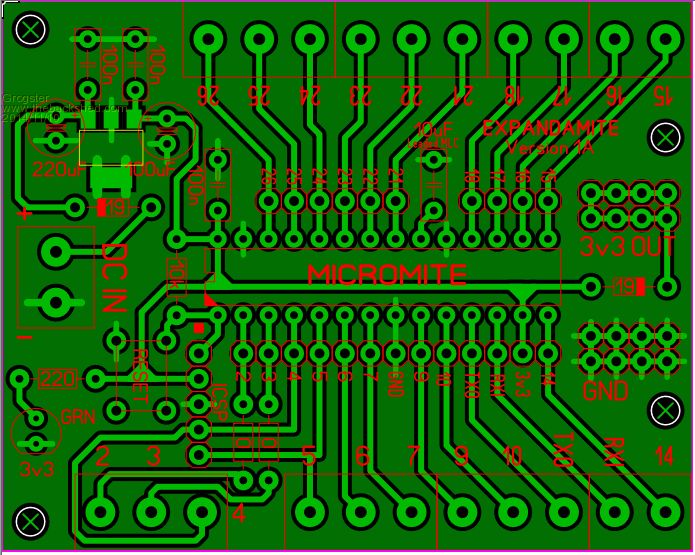
PCB terminal block connections on outer edges, pin-headers close to chip, ISCP, on-board regulator and DC output bus-bars. The only thing I could not squeeze in, was the DC socket, but this is the first attempt... Smoke makes things work. When the smoke gets out, it stops! |
||||
| G8JCF Guru Joined: 15/05/2014 Location: United KingdomPosts: 676 |
Hi Grogster Still a wee bit too small IMHO. But the really important thing is that there needs to be a 0V terminal for every I/O terminal adjacent to the I/O terminal (or use double stacked terminal blocks if length is an issue), otherwise the wiring on the field side tends to become a real mess. Peter The only Konstant is Change |
||||
| Grogster Admin Group Joined: 31/12/2012 Location: New ZealandPosts: 9980 |
For field kind of work, I tend to use bus-bars for that kind of thing. If you have a bus-bar for ground, supply and 3v3, you can wire up any way you like, to your hearts content, and not have to worry about having ground and/or supply connections beside each I/O or the lack thereof. Same bare brass bus-bars that the electricians use in distribution boards or sub-mains. They are quite cheap from the wholesaler, and usually have upwards of twenty separate grub-screws on them - all the common's or supply connections you should ever need.
I have actually done installs like that, and what works for the sparkies, works for the techies too.  With cable-ties and anchor points, your installed wiring can be very neat and tidy, but still easy to get at. With cable-ties and anchor points, your installed wiring can be very neat and tidy, but still easy to get at.
It all depends on what you need to do at the end of the day, I suppose. Smoke makes things work. When the smoke gets out, it stops! |
||||
| robert.rozee Guru Joined: 31/12/2012 Location: New ZealandPosts: 2534 |
the problem with ground connectors for every i/o is cost (for the DIYer), as well as much increased PCB size if using 0.2" screw terminals. grogster: what you have come up with is very close to what i had in mind. but (of course!) there are a few changes i'd suggest: 1 - bring the console out to just a separate 6-pin 0.1" header with 5v, 3v3, TxD, Rxd, gnd. use 6-pin as the back shells are far easier to obtain than 5-pin. 2 - i'm wondering if ICSP can be dropped. there are already the pin headers there, so building a cable to plug into these for programming might be sufficient. 3 - remove the 3v3 trace under the micromite. replace it with a wire link. the trace divides up the ground plane to create a couple of rather nasty looking ground loops. 4 - i much favour a TO-220 regulator, LM1117-3v3 or similar. even if just providing the 3 holes for the TO-220 pins laid over the SOT-223 footprint. below is a terminal layout i came up with last night, very similar to yours: 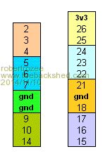
rob :-) |
||||
| Grogster Admin Group Joined: 31/12/2012 Location: New ZealandPosts: 9980 |
Yep, I can look into that. I'm just playing around, really. As to the regulator, I looked at Jaycar, but they only do a 50mA regulator that can accept 9-12v input. 50mA would probably do, but I figured a bit more capacity would be handy for powering other 3v3 things you want to connect to the uM circuit. Jaycar don't seem to sell the 1117, but element14 do here. WHY do you favour the 1117? The SOT223 reg I have designed in is a Microchip MCP1703-33, and they have a wide input voltage, very low dropout and standby current, and only cost 72 cents each. 
I don't really care what reg is used, but I am just curious why you favour the 1117. Is it cos SMD soldering is too scary? Smoke makes things work. When the smoke gets out, it stops! |
||||
| Page 1 of 5 |
|||||
| The Back Shed's forum code is written, and hosted, in Australia. | © JAQ Software 2026 |
