
|
|
Forum Index : Microcontroller and PC projects : VideoMite 1A...
| Page 1 of 6 |
|||||
| Author | Message | ||||
Grogster Admin Group Joined: 31/12/2012 Location: New ZealandPosts: 9975 |
I've been playing around tonight with Sprint Layout: - VT100 and Micromite in standard DIL format for easy chip swapping if need be. - On-board sockets for VGA, Keyboard, USB, DC in, and composite video output. - On-board 3v3 regulator. Diode-gated USB or DC in power supply for the 5v. - Three strips of header sockets for breadboard jumper wires, small point-to-point circuits or a plug-in daughter-board. - 5v, 3v3 and ground headers for powering external hookups. - Baud-rate blob-pads for setting VT100 speed, and blob-pads for selecting VGA colour. 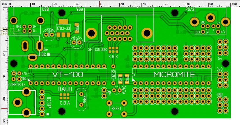
This board is not finished yet - I am just playing, but the idea sprung on me that you may need an embedded MCU with basic video ability all on the one small PCB. Note there is no ICSP header for the Micromite - you just hook up the wires that are needed at the time you need to re-flash - it's not hard, and should not need to happen that often anyway once the Beta testing is finished. I am not trying to re-invent the Maximite. I was just playing around to see if I could squeeze it all into a 100mm x 50mm board, which is quite small, yet still keep the VT100 and Micromite chips as standard DIL. Naturally, I have had to use some SMD, but most of it is thru-hole. It's 4:10AM here, so I need to rest my brain now. Smoke makes things work. When the smoke gets out, it stops! |
||||
bigmik Guru Joined: 20/06/2011 Location: AustraliaPosts: 2981 |
Hi Grogster, Another quality board in the making.. I was just about to send off my artwork for my `corrected' MuP-VT but I think (unless there is a demand) that this would be a more popular option than mine.. A couple of suggestions/observations if I may. It looks Double sided, which is good, I am not a huge fan of single sided. If you reduce the height to 49.5mm then you can lay them out 2 to a 10cm square panel with a 0.5mm gap that can be Vee-Grooved and based on Shenzhen2u prices it would only cost you $3 more to double the QTY of boards. You should be able to add an ICSP header for the uMite along the bottom edge, If you were worried it would conflict with the rows of connections then a R/A header could be installed.. (user choice) Regards, Mick Mick's uMite Stuff can be found >>> HERE (Kindly hosted by Dontronics) <<< |
||||
| Grogster Admin Group Joined: 31/12/2012 Location: New ZealandPosts: 9975 |
Hi Mick. 
Yes, I must say at this point, that I am a new BIG fan of DS(double-sided) board layouts now. I used to do nothing but SS boards, mainly cos I could not do DS board prototypes here at home, but with the price of those overseas PCB houses.... You can't really argue against getting ALL your boards done professionally. Did you have to tell Shenzhen anything special to get them to V-groove your boards? As you probably read, I have them making the other SS board we all developed on the other thread, so we'll see when they get here, and what they look like. As to your suggestions, yeah, I will have a look at squeezing the board height-wise to get two into a 100x100 panel. I also agree about the ICSP header for the Micromite, and looking at the board again today, I also thought the same thing, but you beat me to it!(by suggesting it here before I could) Smoke makes things work. When the smoke gets out, it stops! |
||||
| bigmik Guru Joined: 20/06/2011 Location: AustraliaPosts: 2981 |
Hi Grogs, I didnt tell Shenzhen to Vee Groove, BUT... Here might be the kicker They ask for the GERBERs in a particular format ie. Board outline is name.GML When I create my panelised boards with Autotrax DEX it creates names that are descriptive like Bottom Silkscreen.GBR And the closest I have to Board Outline is Board Profile with Cutouts.GBR so I rename that one to their convention. When I view that one I get a picture like This. 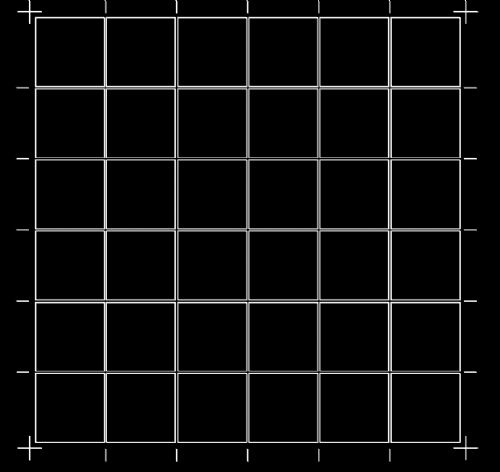
As you can see it is NOT a board Profile (as I would have understood it to mean) but it looks like Shenz uses this information as a Vee Groover. What does Sprint produce for a board outline when you panelise them? Regards, Mick Mick's uMite Stuff can be found >>> HERE (Kindly hosted by Dontronics) <<< |
||||
| Grogster Admin Group Joined: 31/12/2012 Location: New ZealandPosts: 9975 |
It doesn't from what I can see, other then the singular outline file which is the board dimensions, or special shape, but each board is a separate outline. I don't think Sprint Layout supports panellized outlines - I could try drawing an outline around each board on the same panel, I guess - that might be the same thing. Smoke makes things work. When the smoke gets out, it stops! |
||||
| bigmik Guru Joined: 20/06/2011 Location: AustraliaPosts: 2981 |
Grogs, You might be able to CHEAT a bit and create a simple outline of your panels in a SILKSCREEN overlay that looks like the sample I showed you, create your Gerbers and and rename the silk screen to the Board Outline file ... If it was in Eagle I could import it into DEX and panelise it for you.. Unless you can convert sprint to eagle. Mick PS. attached is a file of the board without reduction in case you want to do actual measurements on it. 2014-11-18_005109_Board.zip Mick Mick's uMite Stuff can be found >>> HERE (Kindly hosted by Dontronics) <<< |
||||
| Grogster Admin Group Joined: 31/12/2012 Location: New ZealandPosts: 9975 |
Thanks for that - I will have a play around with things. Layout now has ICSP header for the Micromite chip. Smoke makes things work. When the smoke gets out, it stops! |
||||
| paceman Guru Joined: 07/10/2011 Location: AustraliaPosts: 1329 |
I think this one's a good idea Grogs because we haven't really got a simple all-in-one "development" Micromite board yet (I think?) and this could be it - or it could be used as a standalone project board still, especially if it's kept small. Connecting up side boards all the time makes the work bench messy! You do seem to have quite a lot of room left there and of course no board is finished without suggestions. Here's a few - for a start 
1. Optional spot for a clock, (SMD fine for me) and battery (under?) 2. Optional I2C pullups 3. Vin connector options - can the barrel pad area include screw terminal and/or normal 0.1" header options. 4. At least one 3-pin 5/3.3/Gnd header &/or screw terminal auxiliary out option. 5. 5v protection resistor on the Rx input, or is that already there, cant tell. 6. Does the VT100 need to be DIP? The firmware for that is unlikely to change and to give more room (if needed) you could pre-flash and solder it. 
7. The biggie - a standard 16 pin header for 2004/1602 LCD's? That would mean Vin would need to be 5v, but if a user wanted the LCD they could do that. It would also need a little trim-pot for the LCD contrast and either a pot or resistor for backlight control or resistor and transistor for PWM control. You could go all expensive of course and make them use I2C for LCD's instead.
Greg |
||||
| Grogster Admin Group Joined: 31/12/2012 Location: New ZealandPosts: 9975 |
This was one of the main reasons for playing with this idea, as I got sick of having my Micromite breadboard and VT100 breadboard linked with a spider's web of wire links. 
I did wonder about the RTC, then I just though "Stuff it!" - but it WAS 4AM in the morning, mind.... Would need to be SOIC for space reasons, but I could put the footprint in there - will have a tinker around. Can do, but would have to be via PCB blobs. Will see what I can shoehorn in there. 
Right-side of board, there are three bunches of headers providing six connections each for 3v3, 5v and ground. I assume you mean on the Maximite not the VT100. Can fit one. No, VT100 does not need to be DIL chip, could be SOIC or SSOP. You are right - that is not likely to change much, so I think I WILL change that for a SOIC. Yeah, that one IS a biggie. I would expect that the best compromise would be to just use the header strips as they are for the data lines(which also gives you total control over what lines are used for the LCD via the LCD INIT command), and just have the power, ground and contrast on a separate header.Smoke makes things work. When the smoke gets out, it stops! |
||||
| bigmik Guru Joined: 20/06/2011 Location: AustraliaPosts: 2981 |
G'day Grogs, I too, would do away with the ICSP header for the 250. Why do you need the protection resistor? Given the console is only connected between the two chips. The LCD interface might be too much IMHO. Given different people might want to use different pins... i2C probably would be easy to add, you only need a trim pot additional. Also I2C is not expensive to implement. If you were not stuck for space I would keep the 250 as dip, in fact try to minimise SMD as much as possible as many people are still scared off by SMD. This could be a popular board for newbies to attempt, you would scare them off if it was surface mount.. If you are stuck with a gerber for your outline I could produce one with DEX for you.. I would need exact size of your board to do so... Regards, Mick Mick's uMite Stuff can be found >>> HERE (Kindly hosted by Dontronics) <<< |
||||
| Grogster Admin Group Joined: 31/12/2012 Location: New ZealandPosts: 9975 |
Yeah, I wondered about the resistor on the RXD, but I am GUESSING that if you were to use the console as a 3rd serial port once your code was written etc, then that could be useful. As to the SMD, yeah I think I will just keep it as is so as not to scare anyone off. Do you think it would be a good idea to swap as many SMD parts for thru-hole ones aswell? I can do that quite easily, and can even use a TO220 regulator instead of the SMD one... Smoke makes things work. When the smoke gets out, it stops! |
||||
| bigmik Guru Joined: 20/06/2011 Location: AustraliaPosts: 2981 |
Hi Grogster, But then you would need to disable the connectivity to the '250 else there will be a conflict. That was what I was suggesting.. As you have a heap of room there is no reason to have SMD components.. Not that there is anything wrong with SMD but I think your board will appeal to beginners much more than if it had SMD components.. I feel your board being about the same size as Geoff's VT-100 board but with the added addition of a uMite would/could be a popular first board for many newbies.. Not that I think it is only for Newbies, it is , of course, a good board in its own right.. Mick Mick's uMite Stuff can be found >>> HERE (Kindly hosted by Dontronics) <<< |
||||
| bigmik Guru Joined: 20/06/2011 Location: AustraliaPosts: 2981 |
Grogs, If you can use it, Here is a Gerber file of the board outline I did with DEX. The board is 100mm x 49.5mm and I have them panelised with a 0.5mm separation. 2014-11-18_065015_Board_Profile_with_Cutouts.zip Regards, Mick Mick's uMite Stuff can be found >>> HERE (Kindly hosted by Dontronics) <<< |
||||
| paceman Guru Joined: 07/10/2011 Location: AustraliaPosts: 1329 |
Hi Grogs/Mick, 1. RTC - excellent. 2. Pullups - blobs are good. 3. Vin connect options - excellent again. 4. 3v3/5v/gnd headers - yes there are plenty of connect pads but my thought was convenience. If you wanted to power something via a singe plug and paired wire it would be neater than the separated sets of headers. I'd think they would be better as sets of 3-pin headers rather than the current layout, i.e. like below - or maybe with the 5v/3v3/Gnd aligned horizontally rather than vertically. You two have done this a lot longer than I have though so there may be good reason for it. ------------------------|
| 5v * * *| 3v3 * * *| Gnd * * *| | 5v * * *| 3v3 * * *| Gnd * * *| | ------------------------| 5. Protection resistor - good point Mick, not needed - lazy thought process. Mind you, if there was a reason for someone to connect a console direct into the Maximite, a header and Rx resistor there would be handy. 6. VT100 chip DIL or SMD? - either way I guess, I was thinking of gaining space. SMD is a turnoff for some but as a 0.8mm pitch it's not bad. It's definitely trickier if you need to program it yourself though, but how many would want to do that? 7. LCD header - Umm.. OK - that was an ambit request! I connected one up in a project a few months ago and it was a real pain, so I bought in a couple of those PCF8574T adapter modules (16 pin I/F to I2C) which did only cost me $2 each. When I run out of the couple of standard 20x4 displays I've still got I'll make sure the replacements are serial ones! Greg Edit: you two got back ahead of me here. Edit again: re the point 5 possible conflict - yes it would need links but maybe worth it? |
||||
| bigmik Guru Joined: 20/06/2011 Location: AustraliaPosts: 2981 |
Hi G & G (Greg and Grog), Of course you could use my Blatant plug IO-Panel which has other features as well as LCD.. I can see how you would want all-in-one power headers, personally I prefer as you suggest Greg, for the reasons you mentioned. I think if you use 4pin headers then you could `key' one so that you cannot reverse plug the cable.. The `external Console' would still need the VT chip disconnected from the uMite (even if only the TX pin of the VT chip) or there will be a conflict.. I still dont see a `real' need as the VT chip will work as a console via the USB port anyway. Mick Mick's uMite Stuff can be found >>> HERE (Kindly hosted by Dontronics) <<< |
||||
| paceman Guru Joined: 07/10/2011 Location: AustraliaPosts: 1329 |
Mick, that link's not working for me. Re the direct in to Maximite console: I'm thinking that if you're developing a "standalone" project and run into some issue that you think might be something to do with the VT100 stuff, then cutting it out altogether could help debug things - hardware or software. It would remove another possible (but maybe improbable) variable. Greg |
||||
| bigmik Guru Joined: 20/06/2011 Location: AustraliaPosts: 2981 |
Sorry Greg, Cut and paste `interpreted spaces' somehow Try this one IO-Panel Mick Mick's uMite Stuff can be found >>> HERE (Kindly hosted by Dontronics) <<< |
||||
| paceman Guru Joined: 07/10/2011 Location: AustraliaPosts: 1329 |
Got it. I remember you talking about doing a board like that but don't remember it coming out. Maybe it was during the second half of Sept and into Oct while I was in Sydney for my son's wedding. |
||||
| bigmik Guru Joined: 20/06/2011 Location: AustraliaPosts: 2981 |
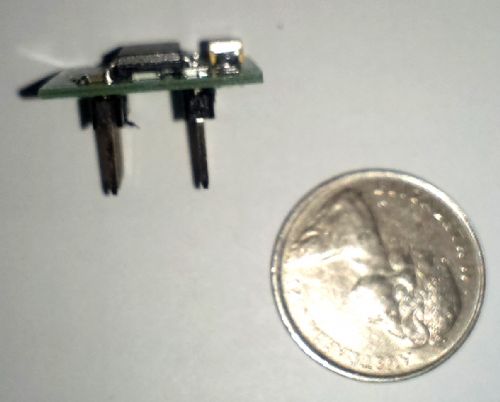
Hi Greg, That is a difficult thing to keep prominent.. I try NOT to self promote and flood the group with what could be construed as ads, although I do have the permission of Gizmo, the site owner, to do so. I sort of prefer `word of mouth' advertising as a more moral method of `self promotion'.. I have considered setting up a cheap web site and then adding a promotion link in my signature, but then I feel that can be over done as well. I try to tread the fine line between letting interested people know what I have available and gratuitous self promotion.. To let you know what I have available I intend to keep this thread up to date every time a new `mick product' is released so that it sort of self perpetuates. Mick's Offerings Regards, Mick PS. I will be, subject to satisfactory testing, when the PCBs finally arrive (expected with in two week) be offering MuP-Mini see the attached prototype photos. FYI That is an Australian 5c coin and the actual boards should be 2mm smaller each dimension. 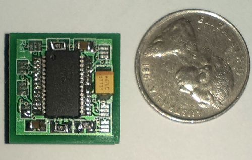
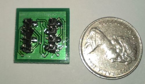
Regards, Mick Mick's uMite Stuff can be found >>> HERE (Kindly hosted by Dontronics) <<< |
||||
| Grogster Admin Group Joined: 31/12/2012 Location: New ZealandPosts: 9975 |
OK, here is the revised board. NO SMD. All parts are thru-hole. Being that there are no SMD, that means there is no RTC chip. I did add footprints for T-block or header power input(0.2" and 0.1" respectively) over the top of the DC socket, so you can choose one of three different connectors to fit for the power input - along with power via USB also. 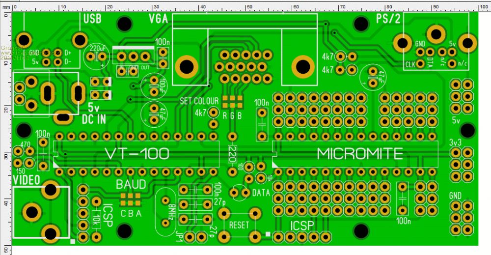
Smoke makes things work. When the smoke gets out, it stops! |
||||
| Page 1 of 6 |
|||||
| The Back Shed's forum code is written, and hosted, in Australia. | © JAQ Software 2026 |
