
|
|
Forum Index : Microcontroller and PC projects : simplest PIC16 ICSP
| Author | Message | ||||
| robert.rozee Guru Joined: 31/12/2012 Location: New ZealandPosts: 2290 |
i've just been trawling through microchips pages to find a low-end PIC that has the following features: - DIP package with at least 14 pins - supports low-voltage programming (LVP) - onboard UART (serial) support - capable of running at 3v3 - readily obtainable, 'old technology' the choice that popped up was an old friend, the 16F628A. many years ago i programmed some of these using a pascal compiler, creating test equipment at a place where i then worked. as i recall, it was all relatively simple and painless, and i was able to get to a finished product within a few days. the goal now, as most have likely already guessed, is to create a bit of hardware attached to a low-end PIC that is capable of both programming code into said PIC, then fairly seamlessly going on to use the programmed PIC to load the micromite firmware into an MX150/170. i've quickly come up with the below circuit, which i am hoping might do the trick: 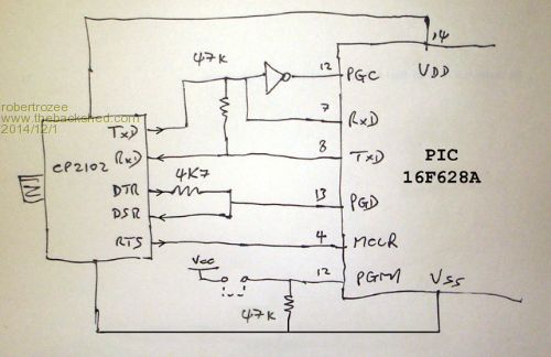
can anyone offer any comments? as far as i can tell, LVP mode is entered just by tying PGM to 5v (assuming LVP hasn't been disabled), with nothing else fancy required. i am not entirely sure if it is even necessary to have MCLR under program control - it may be sufficient to simply insert the jumper before applying power. TxD/RxD are configured to be used either for serial communications (once programmed), or for providing the programming clock. while DTR/DSR are used for reading and writing data to PGD in the same way that john did earlier on with his FT232RL based pic32 programmer. i've not drawn in the part of the circuit where the 16F628A is wired up to the JTAG and ICSP ports on the MX150/170. the first step will be to get code into the PIC16 that simply flashes a LED. cheers, rob :-) |
||||
| MOBI Guru Joined: 02/12/2012 Location: AustraliaPosts: 819 |
Hi Rob, I did what you are trying to do using the PIC16F88 rather than the 628A years ago. The main programme was done in VB6 using an assembler/programmer set up. The PC communicates with the F88 via com port (USB - SERIAL). The F88 contains the routines to activate the SilChip Pic Programmer board. I also have a version using a ATMEGA 328 to programme AVR chips. The system works in a sort of JTAG way using serial commands. I can email you the F88 source code if you like. It is buried in my system somewhere but I should me able to find it. I gave up on the MM/micromite programmer. Might get back to it one day. Far quicker and easier to use the Pickit3. Besides I had already done similar in the F88 project so I know what you are wanting to do is easy enough. I must warn that even the 8 bit version was quite slow at programming another 8 bit chip, but ok all the same. David M. |
||||
| robert.rozee Guru Joined: 31/12/2012 Location: New ZealandPosts: 2290 |
mobi: were you able to program the ATMEGA 328 without it needing to have a bootloader already loaded? if you could, i am sure this would be of great interest to the arduino fraternity! i would be very interested in seeing the circuit you used, and perhaps the VB6 code. the F88 code is not quite so important, as the code being uploaded to the 628A would implement either my 'ascii JTAG' protocol, or peter's loader. comparing the features of 16F88 and 16F628A shows up no great advantage of one over the other in the application of a PIC32MX programmer. the 16F88 does have an internal oscillator that can run at 8MHz, but then costs much more and seems less readily available on ebay. if anyone could suggest a better choice of PIC to use, please do speak up. cheers, rob :-) |
||||
| MOBI Guru Joined: 02/12/2012 Location: AustraliaPosts: 819 |
Yes. I have mentioned in a much earlier post that I started with home grown pic programmers when I bought a laptop which of course didn't have a hardware com port and trying to do the same thing using a USB Serial cable was excruciatingly slow. So I jigged up a VB6/pic16F*** set up that could assemble a text file and programme an 8 bit pic. I got interested for a while in Atmel and modified the pic programmer and VB6 to handle AVR programming commands. Next step was to replace the Pic interface with a AVR. Then I bricked the 328 chip (wrong oscillator fuse byte) which meant programming in HV mode - that meant switching the VDD and VPP under programme control. It sort of worked. The I thought I'd have a go at Arduino since I could now programme an AVR chip - found the appropriate bootloader HEX file that came with Arduino and dumped it in and it worked quite nicely as an Arduino chip. That was some years ago and as it was just a series of experiments, I put it to bed not expecting to need it again as my interests had moved on. I still have most of the data but it is not too well documented. I'll see over the next few days if I can put a ZIP file of relevant diags and code together. Regards. PS. PIC16F819 is cheaper than F88 and almost identical (no ADC). I got my chips from Modtronix (Sydney). Prices don't look too bad but are not like the 50 cents or so I paid a few years ago. David M. |
||||
| MOBI Guru Joined: 02/12/2012 Location: AustraliaPosts: 819 |
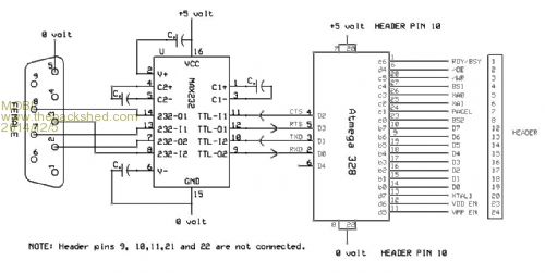
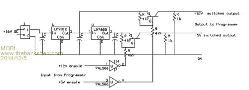
Hi RoB et al, Here's some schematics. I didn't have any MAX232 chips when I built the first pic programmer serial interface but had some 4049 inverters which combined with some diodes and resistors worked quite well. Later versions used MAX202 (same as 232)on the AVR programmer experiment so you could always swap over the serial interface input circuit. Included in the zip file is the VB6 source that talked to the programmer. I have left out the GUI bits and pieces as not everyone has VB6. The VB6 code was written to perform assembler functions from a text file and also programme 8 bit PICs. It is quite difficult to read but there are bits that could be extracted and used in say a MaxiMite run version and leave the PC out of the picture other than to produce the hex files and out on SD card. The voltage switch is rather rudimentary but works good enough. I used it on the HV mode for the AVR project after I bricked the 328 chips. (need HV to reset fuses) In the zip file are some images as well as PIC code for the Pic programmer and the AVR programmer. Handshaking between the PC and interface (PIC88) was done using CTS as: while mscomm1.ctsholding = false:wend:....data transfer. You could use a simple MM loop. I hope this helps a bit. Frankly these days I'd buy a pickit3 but then, one doesn't learn much other than how to use the programmer. The fun of the chase? The images in the zip file are much clearer. 2014-12-05_005429_avr_pic_programmer.zip 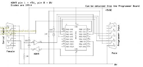
David M. |
||||
| viscomjim Guru Joined: 08/01/2014 Location: United StatesPosts: 925 |
Hello Mobi, its nice to see you here again!!! |
||||
| robert.rozee Guru Joined: 31/12/2012 Location: New ZealandPosts: 2290 |
the info looks interesting. so, given just a blank 16F88 (plus a handful of components), and ONLY a usb to serial bridge (ie, no "real" serial port), the first circuit in the above posting is sufficient to get one to the stage of having code programmed into the 16F88? cheers, rob :-) btw, the first circuit doesn't appear to be in the zip file. |
||||
| MOBI Guru Joined: 02/12/2012 Location: AustraliaPosts: 819 |
Thanks Jim. I've been a bit busy - still am. @Rob. Well, sort of - unfortunately no free lunch. If you want to use the PC to decode and output the hex file and actuate the serial control pins like your simplest pic32 icsp, you can but it is terminally slow and you might have problems with the break line I think it was. If you want to speed thing up and use a pic interface to do all the signalling then no. You will still need to programme an interface pic. That is how I started when laptops no longer had Comm ports. I was able to use my assembler/programmer programme (the VB6 source in the zip) to programme the interface pic and then use the newly programmed pic in conjunction with the PC assem/prog suitably modified. It didn't happen over night. I have updated the zip and I think I have the right cct diag in now. 2014-12-05_043234_avr_pic_programmer.zip 2014-12-05_070016_silicon_chip_pic_programmer.zip David M. |
||||
| robert.rozee Guru Joined: 31/12/2012 Location: New ZealandPosts: 2290 |
i'm not entirely sure that, with some clever programming and simple hardware, there isn't the chance of at least a very cheap lunch to be had. see the following circuit, which combines a PIC16F6XXA programmer with a 32MX programmer. active components are 1 NPN transistor and the 628A: 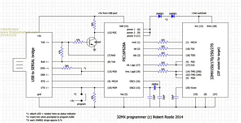
2014-12-06_105458_ckt.pdf to program the PIC16F the user runs a single firmware upload executable. this operates thus: 1. sets RTS low. this holds the PIC16F in reset. 2. prompts the user to insert the program jumper. 3. when it sees the program jumper is in place (via CTS) the firmware uploader raises RTS. the PIC16 is now in low-voltage programming mode. 4. PGD on the PIC16F is controlled by DTR. it is read using DSR. whenever the state of DTR is changed the firmware uploader waits to see DSR reflect the new state. 5. PGC clock pulses to the the PIC16F are effected by sending character 0xFF out TxD from the PC - this produces a short negative going pulse that is inverted by the NPN transistor into a short positive clock pulse. the firmware uploader pauses after sending each character to see it looped back via the 47k resistor between TxD and RxD. 6. once the firmware uploader has completed the upload (and any verify) it instructs the user to remove the program jumper. it then resets the PIC16 and exits. 7. code within the PIC16F flashes an LED attached to pin 13 to indicate that the firmware is running. to program the 32MX requires using a modified pic32prog or similar. data sent out TxD from the PC goes to pin 7 (RxD) on the pic16F, while data send out pin 8 (TxD) is received by RxD on the PC. in this configuration the 47k resistor between TxD and RxD will have no effect. the PIC16F runs a firmware that responds to ASCII commands ('d', 'e', 'f', 'g', 'D', 'E', 'F', 'G') that encode TDI/TMS pairs and responds with '0' or '1' if required to report the state of TDO. this has been well tested using a micromite running in place of the PIC16F. the protocol is called "ascii JTAG". there is also provision in the hardware design to program the PIC32 via ICSP later on. currently, ICSP is used only to erase a PIC32 that has had JTAG disabled in the configuration words. there is no reason why the protocol used by peter (G8JCF) could not be implemented. if a PIC16F648A is used, there is 4k words of program space available for the firmware. no special functionality of the PC serial port is used - any USB to TTL serial bridge should work. access is provided by windows/linux to DTR, DSR, RTS, CTS through system calls, while there is no longer any need to generate a break on TxD as this pin is only used to generate clock pulses (by sending out character 0xFF). and speed of programming the PIC16F is of little concern, as this will generally only be done once. would others care to check out my circuit for any errors? once it has been 'peer reviewed' i'll start looking at putting together the firmware uploader. from reading through MOBI's code and the PIC16F programming manual, this seems to be relatively simple. cheers, rob :-) |
||||
| MOBI Guru Joined: 02/12/2012 Location: AustraliaPosts: 819 |
@Rob On the surface, it looks workable. I like the use of TxD as the clock generator sending &Hff to produce a single pulse (the start space). In the Silicon Chip programmer, TxD was toggled to switch VPP (13.6v) to the reset pin and when used on a USB serial cable, had a problem that the "break" function would toggle when there was any activity on the serial control lines. I think that was a problem with VB6 MsComm. I ended up using the Windows API comm port function to overcome it (before building the serial version). As you are likely to only programme the 628A once, there is probably no need to consider what happens when the config byte stuffs up the LVP bit and won't programme anymore without using HV programming mode. Accidents do happen. David M. |
||||
| robert.rozee Guru Joined: 31/12/2012 Location: New ZealandPosts: 2290 |
mobi: it would be relatively simple to allow for HV programming by installing a removable link in the connection between RTS and pin 4 (-MCLR) on the PIC16F. then instead of installing the 'program' jumper when instructed, connect 13v to pin 4. CTS would also need to be rewired a little, or just ignored (could be handled with the firmware uploader having a 30-second timeout on monitoring CTS before carrying on anyway). i used the Silicon Chip programmer many years back. it worked extremely well. i'm really surprised that they used TxD as a switched line instead of to generate PGC, as this one change would have allowed their programmer to continue working with USB connected serial ports. there is a temptation to send the above circuit, with the 32MX part removed, to the author of 'picpgm' and ask him if he would care to expand the program to support this programming scheme. it would remove another step needed to get everything up and running. also, a question for the experts out there: does mplab X have a C compiler bundled with it that can generate code for the PIC16F devices? cheers, rob :-) |
||||
