
|
|
Forum Index : Microcontroller and PC projects : Flexible PIC18/Micromite development PCB
| Author | Message | ||||
| matherp Guru Joined: 11/12/2012 Location: United KingdomPosts: 11516 |
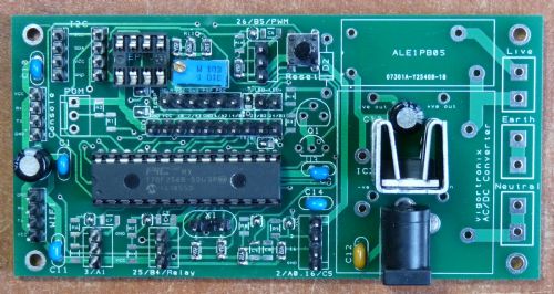
One of the things which helps software development productivity is having a flexible and easy to configure hardware platform. In this case my board is also designed to be a complete solution for individual finished projects by part populating the components as required. There are three areas of flexibility in this design: Single or Dual voltage AC or DC Input Power supply 28-pin PIC32 or PIC18 or PICAXE processor Highly Configurable I/O ports The power supply section supports: AC mains input using one of the Vigortronix AC/DC convertors. I've used the Vigortronix VTX-214-003-105 3W AC-DC Power Supply Single Output 5V together with a TC1264 LDO regulator in the U3 position to provide both 5V and 3.3V rails. DC input with dual or single rail output using 7805 compatible regulators. I use UA78M33C for direct regulation to 3.3V and TC1264 if deriving 3.3V from a 5V rail. DC input using one of the Ebay mini switching DC/DC boards(e.g. item 301148261237, but available much cheaper from China) direct to 3.3V or to 5V and then secondary regulation to 3.3V if required. The use of the dual rail supply allows the circuit to drive a high power(16A)/high voltage(240VAC) relay (the PCB pinout is for the ALE1PB05 ) via a BCX38 darlington transistor. If this isn't required direct regulation to 3.3V is the best option, particularly now 3.3V LCDs are available (search ebay for suppliers) There is a shorting link on the bottom of the board which bypasses the second regulator for single rail operations. The processor flexibility is achieved by using 14 small two-way shorting links which control the way that the processor pins are connected to the peripherals. The connection to the end marked with a "*" on the board is for PIC18/PICAXE, the other end is for PIC32. Although this seems like a lot of configuration it takes less than a minute to do and all the links are either at the "*" end or the other. Doing this allows pins such as ICSP, I2C, and hardware serial I/O to be correctly routed. There is an 8 pin socket position on the board for an EEPROM such as the 24LC512. (External address lines pulled low) There are I/O headers on the board for: 2 * I2C 1 * parallel LCD + 1 * LCD backlight via current limiting resistor Micromite Console HW serial (marked wifi - the layout matches the wifiuart I use) ICSP 3 * 3 pin ports (VCC,port,GND) with optional series resistors, pullups, RC filters, or direct connection 1 * 4 pin port (VCC, port, port, GND) with the same I/O flexibility on the ports as the three pin PICAXE 3 pin programming port Mains input including relay switched live and loop through earth and neutral. For the PIC32/Micromite the PIC18 XTAL pins can be used as extra I/O ports with optional pulldown resistors replacing the Xtal capacitors as seen in the picture. Of course any of the ports can be used for any purpose within the limits of what the processor chip can do so the LCD port can just be used as 6 direct pin connections. All components are through hole with the exception of easy-to-solder 1206 resistors and capacitors for the I/O. The PIC32 VCAP is the only component on the bottom of the board and is another 1206 part. The attachments include the design files (Designspark) and a ZIP of the complete set of gerbers as sent to ITEAD Studio who fabricated the board for me ($14.90 for 10 off 10cm x 5cm green 1.6mm PCBs) 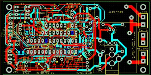
2014-12-03_104441_micromite.zip 2014-12-03_104500_WifiBoard.zip |
||||
bigmik Guru Joined: 20/06/2011 Location: AustraliaPosts: 2981 |
Hi Matherp, Nice looking board, Can you provide some PDFs (esp the schematic) as I cant read your PCB file format. Regards, Mick Mick's uMite Stuff can be found >>> HERE (Kindly hosted by Dontronics) <<< |
||||
| viscomjim Guru Joined: 08/01/2014 Location: United StatesPosts: 925 |
Pretty nice board there Matherp. I would like to see sch. also if you are willing to post it. |
||||
| matherp Guru Joined: 11/12/2012 Location: United KingdomPosts: 11516 |
Schematic attached as requested together with higher resolution layers picture. 2014-12-04_090217_WifiBoard_-_Project.pdf 2014-12-04_090156_WifiBoard_-_PCB.pdf |
||||
| The Back Shed's forum code is written, and hosted, in Australia. | © JAQ Software 2026 |
