
|
|
Forum Index : Microcontroller and PC projects : uMite Reflow oven
| Page 1 of 2 |
|||||
| Author | Message | ||||
| viscomjim Guru Joined: 08/01/2014 Location: United StatesPosts: 925 |
Feeling inspired by BigMiks nanomite, I am starting to put together the components to make a toaster oven reflow oven for soldering surface mount parts. I want to use a thermocouple amplifier for feedback back to the uMite used as a pid controller. I was going to use the MAX6675, but according to adafruit, it is a discontinued device, and they suggest the new MAX31855. Both devices are SPI interface. The problem with the new chip is that it spits out 32 bits of data and the uMites SPI command will do 8 or 16 bits. Has anyone had any experience with this type of unit, should I just stick with the 6675? or is there a way to do this 32 bit dealio? |
||||
jman Guru Joined: 12/06/2011 Location: New ZealandPosts: 711 |
Hi And the good news is that from beta 16 "The SPI function can now send/receive data in 32 bit blocks (in addition to 8 and 16 bits)" Regards Jman |
||||
| viscomjim Guru Joined: 08/01/2014 Location: United StatesPosts: 925 |
Hi Jman, I guess its time to print out the new manual. Thanks for that, one thing out of the way... |
||||
Grogster Admin Group Joined: 31/12/2012 Location: New ZealandPosts: 9980 |
I used the AD595 which outputs and analog voltage depending on the thermocouple temperature. This is dead easy to read with any analog pin. I found my AD595's on eBay. Smoke makes things work. When the smoke gets out, it stops! |
||||
| paceman Guru Joined: 07/10/2011 Location: AustraliaPosts: 1329 |
Jim, did you see Peter's (@matherp) code for type K thermocouples here: Type K code. Remember you need to have an accurate cold junction temperature measurement to get accurate temperatures from thermocouples, otherwise your reported thermocouple temperature will move with the temperature at the connector (cold) end of the chromel/alumel wire - usually ambient, but if in a toaster probably a lot more.  Peter's code uses a DS18B20 for the cold junction which makes it easy for us. Peter's code uses a DS18B20 for the cold junction which makes it easy for us.
Greg |
||||
| viscomjim Guru Joined: 08/01/2014 Location: United StatesPosts: 925 |
Thanks for that. I will check it out. So far the max31855 seems pretty good for this application. EDIT... The units have the description as cold-junction compensated thermocouple amplifiers. So I am assuming that this is somehow taken care of. I will keep digging to find out more... |
||||
| paceman Guru Joined: 07/10/2011 Location: AustraliaPosts: 1329 |
I should expand that post above a bit. The thermocouple (T/C) chips themselves do have cold junction compensation built in but that assumes you are connecting the actual T/C wire directly to the chip, or are using "compensating" wire, not copper wire, between the thermocouple wire and the chip. Compensating wire is normally just T/C wire that failed the tight alloy specification for each 'proper' T/C wire and is consequently sold cheaply, but few non-industrial users (like us) would bother with that. This means that if you use a copper wire connection between the T/C wire and the chip, you need to make sure that the temperature of the T/C-copper wire junction is the same as the chip temperature, otherwise the difference between those temperatures will be applied to your readings  . If those temperature differences are small it's of little consequence but they're often not as I found out early in my metallurgy career. The cold junction compensation built into the chip will still be getting applied to the reading but it is assuming that the T/C wire or "compensating" wire is connected directly to the chip. . If those temperature differences are small it's of little consequence but they're often not as I found out early in my metallurgy career. The cold junction compensation built into the chip will still be getting applied to the reading but it is assuming that the T/C wire or "compensating" wire is connected directly to the chip.
Greg Edit: BTW I noticed that the MAX6675 can use 3.3v or 5v but the MAX31855 can't use 5v. Also maybe more importantly the 6675 "Typical Application Circuit" shows a grounded T/C but the 31855 circuit shows an un-grounded T/C. @matherp's code that I linked in the post above requires the use of an un-grounded T/C connecting to the ADC (note this not a thermocouple chip per se). Greg |
||||
bigmik Guru Joined: 20/06/2011 Location: AustraliaPosts: 2981 |
Hey I am glad there was someone inspired, 
I was thinking about the reflow oven and I would love one, and may get one if this project gets completed, but after building 3 NanoMite's I can honestly say the hardest part is soldering the SMD square pins on the underside as the NanoMite is so small it moves if you breathe on it.. Once the SMD square pins are soldered they can be plugged into a bread board (I used a ZIF Socket panel that came with my PicKit3) to hold the PCB still whilst soldering the top components (While wearing High Mag glasses). A reflow oven `I think' would melt the plastic of the SMD pins so it wouldn't help that part. BTW I found those reverse style tweezers magnificent for clamping the small parts down whilst soldering. Regards, Mick Mick's uMite Stuff can be found >>> HERE (Kindly hosted by Dontronics) <<< |
||||
| jman Guru Joined: 12/06/2011 Location: New ZealandPosts: 711 |
Hi I am also keen to build a reflow oven. So lets make a project and get on with it. The Max31855 work really well as I happened to have one in the draw here is some working code [code] '''''''''''''''''''''''''''''''''''''''' 'Max 31855 Dim temp32%(32) Start: '''''''''''''''''''''''''''' 'Spi Read 32 bits Pin(26) = 1 : SetPin 26, Dout SPI Open 40000, 0, 32 Pin(26)=0 SPI Read 32, temp32%() Pin(26)=1 SPI Close Temperature%=Temp32%(0) >> 18 'sh*t out unwanted bits error = temp32%(0) And &B111 'Error check If error <> 0 Then Print "Thermocouple Error" Pause 5000 GoTo Start EndIf DPoint = Temperature% And &B11 'Remainder DPoint = Dpoint *.25 Temp = (Temperature% >>2) + Dpoint 'sh*t out remaninder Print Temp;" C" Pause 5000 GoTo Start [/code] |
||||
| Grogster Admin Group Joined: 31/12/2012 Location: New ZealandPosts: 9980 |
Hahahahahaha!!!!!  Smoke makes things work. When the smoke gets out, it stops! |
||||
palcal Guru Joined: 12/10/2011 Location: AustraliaPosts: 2039 |
@bigmik In my opinion a reflow oven would be really useful for large boards, but as Geoff suggested very early in the piece in the original Maximite days get a binocular microscope. I bought one from the US for about $120.00, put your board on it and an SMD looks like a house, mind you the soldering iron looks like a crowbar but it has 2 spring loaded arms that hold down the device being soldered and makes the whole job so easy. Paul. "It is better to be ignorant and ask a stupid question than to be plain Stupid and not ask at all" |
||||
| matherp Guru Joined: 11/12/2012 Location: United KingdomPosts: 11585 |
The issue with grounded probes is that you can't measure temperatures below the cold junction with a grounded probe unless you have a dual rail amplifier with gnd in the middle. Otherwise the thermocouple output will go below the gnd rail to the chip which may even take it outside of safe operating limits. |
||||
| jman Guru Joined: 12/06/2011 Location: New ZealandPosts: 711 |
As per the data sheet "The MAX31855 performs cold-junction compensation" Jman |
||||
| paceman Guru Joined: 07/10/2011 Location: AustraliaPosts: 1329 |
Yes, but the issue of temperature differences is still there if you use a copper wire connection to the chip. If the T/C wire is connected direct to the chip it will correct accurately. If you have the T/C wire connected to copper wire and then the copper wire connected to the chip any difference in temperature between the two connecting points will directly affect the readings. Greg |
||||
| viscomjim Guru Joined: 08/01/2014 Location: United StatesPosts: 925 |
Thanks for the code Jman. I was checking out the arduino library on that one and noticed as you did the 18 bit shift to get to the temperature on the probe, you can also do a shift (i think its 4) and get the internal temperature also. Not sure if this is of any value in this project. I am basing my uMite project on code I found here. This was written in picbasic and should be very easy to port. Has a nice description of the pid routine also. The code has been updated since this project was posted. The new code is on github and is here. For the 5 switches that are used for up down previous next and enter, I will be implementing one of these. 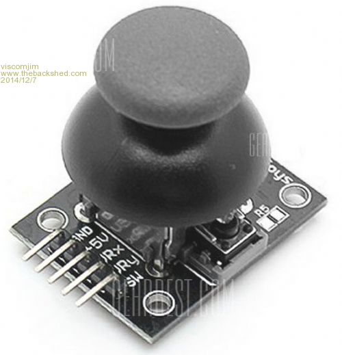
I hooked one up to uMite using 2 analog inputs and one digital (can be interrupt too), and just by checking range using > or <, you can easily use it as 4 switches, or even 8 if you read both x and y for the corners and use the push switch for enter. These are quite inexpensive and look really cool too. Obviously they can also be used as analog joysticks also... but for this project it will just be 5 position switch using 3 inputs. |
||||
| jman Guru Joined: 12/06/2011 Location: New ZealandPosts: 711 |
Here you go this will also show the reference temperature [code] '''''''''''''''''''''''''''''''''''''''' 'Max 31855 Dim temp32%(32) Start: '''''''''''''''''''''''''''' 'Spi Read 32 bits Pin(26) = 1 : SetPin 26, Dout SPI Open 40000, 0, 32 Pin(26)=0 SPI Read 32, temp32%() Pin(26)=1 SPI Close error = temp32%(0) And &B111 'Error check If error <> 0 Then Print "Thermocouple Error" Pause 5000 GoTo Start EndIf Temperature%=Temp32%(0) >> 18 'Shift out unwanted bits IntTemperature%=Temp32%(0) >> 4 'Shift out unwanted bits IntDPoint = IntTemperature% And &B1111 'Remainder IntDPoint = IntDpoint *.0625 IntTemp = ((IntTemperature% >>4) And &B11111111) + IntDPoint Print "Reference Temperature ";IntTemp;" C" DPoint = Temperature% And &B11 'Remainder DPoint = Dpoint *.25 Temp = (Temperature% >>2) + Dpoint 'Shift out remaninder Print "Measured Temperature "Temp;" C" Pause 5000 GoTo Start [/code] Regards Jman |
||||
| Grogster Admin Group Joined: 31/12/2012 Location: New ZealandPosts: 9980 |
While we still have a semi-active reflow oven thread, here is my one: 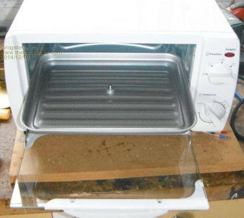
The thermocouple is bolted to the middle of the toaster oven tray. As these cheap toaster ovens have no thermal insulation like a proper house kitchen oven, it was a simple matter to drill a hole in the back of the oven to pass the thermocouple cable out of. I picked up the toaster oven for $15 new at a warehouse sale. The controller PCB - top: 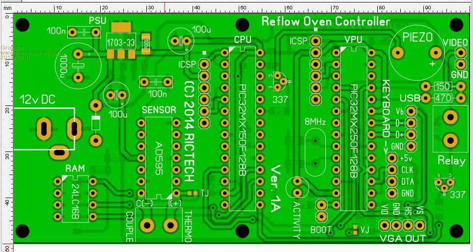
...and bottom: 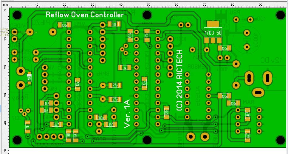
This controller has the 595 thermocouple amp, a Micromite CPU and a VT100 all on the one board. With the VT100's nice big font options, the plan is to couple this up to one of those dinky wee composite video displays that can be had on eBay for $50 or less. I could have used an LCD, but am so in love with the VT100......... Smoke makes things work. When the smoke gets out, it stops! |
||||
TassyJim Guru Joined: 07/08/2011 Location: AustraliaPosts: 6541 |
I bet WW is hoping for a toaster oven as a wedding present.... Jim VK7JH MMedit |
||||
| paceman Guru Joined: 07/10/2011 Location: AustraliaPosts: 1329 |
He'd probably like it better than his intended would - wishing well anyone?
Greg |
||||
| viscomjim Guru Joined: 08/01/2014 Location: United StatesPosts: 925 |
Holy Cow Grogster, you are really attacking it! I think the vt100 add on is a great idea. I've been slowly digesting the pic code referenced earlier and am hoping that the pid tuning process won't be too crazy. I have built a few CNC machines in my day and tuning the closed loop servos could be a tedious undertaking. With the new servo amps out there, at least you could change values in your pid setup and do a test move and get an instant plot of the servos response to the changes in the pid. Even with this, it could sometimes take quite a while to get a nice tight control loop reponse. My fear with tuning the pid in the oven is that obviously, each change of pid and subsequent test could take quite a few minutes each to get the result of the change. This could be interesting. I have also looked at this and read their user manual and saw a video on eeblog (dave?) about this unit. It seems that you can hook this unit up to your oven, run a quick "learning" routine and its tuned. So I am guessing that just by turning the oven on full blast and reading the thermocouple over time till it gets to full temp. gives this thing enough info to create a pid profile. That has got to be a bit of crazy math. As this has a port to hook to a pc, some ingenious guy wrote a little program to watch the progress of the oven using the beta unit as it heats up here I will keep on getting my controller and oven going and during that time I hope to get a better handle on the tuning thing. There is quite a bit of info on diy reflow ovens out there, and alot of it is arduino based. They even have a pid routine and I think I saw an auto tuning routine also. Keeping fingers crossed... |
||||
| Page 1 of 2 |
|||||
| The Back Shed's forum code is written, and hosted, in Australia. | © JAQ Software 2026 |
