
|
|
Forum Index : Microcontroller and PC projects : MM2: Yet another,another PCB for 44-pins
| Author | Message | ||||
| matherp Guru Joined: 11/12/2012 Location: United KingdomPosts: 11499 |
I'd appreciate feedback on the attached design. The intention is to support development and individual project use for the Micromite MK2. In this case I'm using the 44-pin variant to give much more flexibility. The intention is that it is very easy to directly connect and power multiple external devices, SPI, I2C, LCD, analogue, DS18B20, IR, HC-SR04 etc. where they may require 3.3V and/or 5V supplies without any external components. This is my major complaint with most "development" PCBs available across many platforms. For example connecting the signal lines to an Arduino is easy but adding pull-up resistors is a nightmare without an additional shield. The console port is laid out to allow direct connection of one of the 4-pin cheapo USB adapters without getting in the way of any of the other headers The layout of the board allows it to be directly connected to a standard LCD display as a sort of "jumbo" backpack with the components positioned away from the LCD. The board has options for pullups, pulldown, RC filters, current limiting resistors, or direct connection to a range of the most flexible Micromite pins. The two SPI headers have 3 additional pins on each allowing for uses such as chip-select, data/command, reset as required by the specific device. The layout includes a battery backed PCF8563 RTC. The idea is that the board is only populated to the extent required for a particular development or application. The board also has the ability to switch high power high voltage loads using a relay. The layout and routing was all hand done with no traces below 10 thou and all power lines at 50 thou. Minimum spacing between tracks is at least 10 thou in all places. I don't know about other design tools, but DesignSpark is completely incapable of making any useful attempt at autorouting a board like this. All pins are fully silkscreen labelled so it should be easy to use the board without reference to the schematic. I can post Gerbers and Designspark files if anyone wants them. Positive and negative feedback greatly appreciated. 2014-12-09_184748_MM2-_PCB.pdf 2014-12-09_184806_MM2-_Schematic.pdf |
||||
| viscomjim Guru Joined: 08/01/2014 Location: United StatesPosts: 925 |
Hi Matherp, first of all, very cool design. Does design spark give you a PCB view or 3d view or something. Just curious to see what the board looks like populated. |
||||
| matherp Guru Joined: 11/12/2012 Location: United KingdomPosts: 11499 |
DesignSpark PCB can export to DesignSpark mechanical which I presume could then do a 3d view. However, this would rely on there being 3D models of the various components which is certainly not the case for many of them (e.g. the regulators with heatsinks). Also this is way outside my competence level in using the tool. Forgot to mention board size is exactly 10cm x 5cm so USD14.95 from Itead Studio for 10 off. Itead have been very good on all my designs so far, good quality and fast production. They claim to test each and every board against the net list and certainly so far I haven't had a fault of any sort when using Designspark to generate the gerbers on a layout that its "Design Rule Check" has approved. |
||||
| paceman Guru Joined: 07/10/2011 Location: AustraliaPosts: 1329 |
That looks a handy concept Peter, especially at 10x5, and comprehensive too. I think catering for the std 16 pin LCD is good idea; they're a pain to hook up otherwise and often needed. Here's some points that might be relevant. 1. Might be worth catering for PWM control of the LCD backlight too, as well as the fixed resistor. It would mean an extra transistor but a lot of designs will use PWM for it. 2. You've got the Darlington drive for the relay there already, why not have a pin/pad available between the two for external relays that don't need the big one. Not sure if it's best active high or low a la Arduino. 3. Mick's 1K protection resistor on the console Rx pin would be a good idea in case someone hooks up a 5v USB/TTL lead. Greg |
||||
centrex Guru Joined: 13/11/2011 Location: AustraliaPosts: 320 |
Hi Matherp A very nice looking board except for a couple of concerns..... The area marked live,neutral and earth if this is intended to be connected to mains voltage as the names suggest it could be lethal without adequate shielding. The scl line to the rtc (pcf8563) appears to be on another layer dark blue with no way to get to the top layer which I assume is the red. The close proximity of the rtc xtal to a heat source (VCC reg)could cause a stability problem. Just my thoughts Regards Cliff Cliff |
||||
| matherp Guru Joined: 11/12/2012 Location: United KingdomPosts: 11499 |
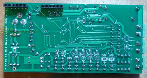
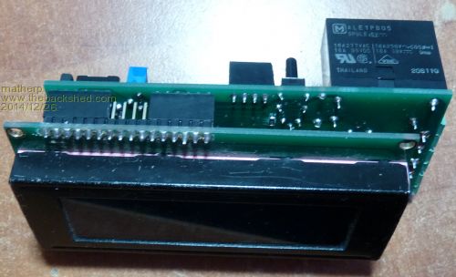
I got the boards back from Itead Studio just before Christmas and got a chance to build one up today. For test purposes I fully populated it. Overall I'm quite pleased with the result. Everything works as it should. I didn't make any changes from the original circuit but take on board the comments from paceman - good ideas for V2. centrex: Obviously care must be taken if switching mains. However, the clearances meet normal standards so the critical thing is the housing if used in that way. The dark blue line is just an artifact of that net being highlighted when I took the picture. The VCC reg is only ever used to drop from 5V to 3.3 so heating shouldn't be too much of an issue but I'll look at the layout if I do another version. The VEE reg does the main work and if only 3.3V is required the regulator goes in that place and the VEE-VCC bypass link is installed. The pictures show both sides of the board and also it in use as an LCD backpack. 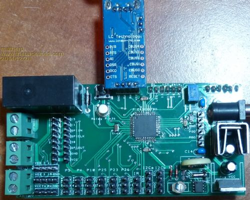
|
||||
| The Back Shed's forum code is written, and hosted, in Australia. | © JAQ Software 2026 |
