
|
|
Forum Index : Microcontroller and PC projects : MM2: Updated graphics - All controllers
| Page 1 of 2 |
|||||
| Author | Message | ||||
| matherp Guru Joined: 11/12/2012 Location: United KingdomPosts: 11602 |
I've updated all the graphics routines with additional cFunctions. The only significant Basic code left is now the filled-triangle routine. I've also further optimised the 2.4" TFT cFunctions. There is a Youtube video I found of the Arduino writing a 100-pixel radius circle in response to a touch input. The Micromite code appears to run at least 5x as fast doing the same thing. If you are playing with previous versions of code for any of the supported controllers, please update. These routines are now finished (he says hopefully  ). ).
Included in the zip are files for the: I2C SSD1306 OLED SPI SSD1306 OLED SPI NOKIA5110 LCD, PCD8544 controller 1.8" TFT SPI colour, ST7735 controller 2.4" TFT parallel colour, ST7731 The graphics primitives and cFunctions for the monochrome displays are all identical (just renamed in the Nokia example). These update an internal memory map of the display (needed because there is no mechanism for updating a single pixel, only eight-at-a-time). Then the same "update" cFunction packs a string with bytes for output which is done from Basic in the "refresh" routine using either SPI or I2C as required. To support one of the graphics LCDs such as the KS0108 should only require the relevant init and refresh routines to be created. The graphics primitives and most of the cFunctions are the same for the two colour TFT displays. There are only two cFunctions that write to the screen, one that updates a single pixel and one that updates a rectangular block of pixels. To support other types of controllers these and the initialisation code will be all that needs to be changed. I believe the ST7731 code should also support the spfd5408 and ILI9320 but would appreciate confirmation if anyone has got one of these displays. The SPI and I2C pins for the monochrome displays are of course fixed. The other pins can be changed in the Basic code by changing the pin definitions. The pin allocations for the colour screens are completely fixed as specified in the Basic code otherwise the cFunctions won't work. In the case of the parallel driven ST7731 display this really needs a 44-pin Micromite as the allocation currently overlaps the SPI, I2C and COMM1 pins. Once I have a 44-pin Micromite up and running I'll provide alternative code for that. In the meantime 44 pin chips can be used if you map the underlying PIC pins using the PIC32MX1XX/2XX datasheet (e.g. pin 2 on a 28 pin part is A0, this is pin 19 on the 44-pin part). The two key controllers I haven't tackled are the ILI9341 and SSD1289 which seem to be used for the 3.2" and bigger displays. I've got one of these on order (don't know which til it arrives) and will implement that as and when. The routines do not handle touch input. This should be done separately. The 3.2" displays have a dedicated SPI touch controller chip and I'll implement code for this once I get the display. The 2.4" and 2.8" displays are mostly built onto Arduino shields and multiplex the touch pins onto display pins. I'm waiting for the final release version of 4.6 to have another go at implementing this. Of course in this case the relevant Micromite pins need to be re-set to DOUT for each display output. Please find attached ZIPs of all the latest versions. If there is a specific similar display you want implemented I could do this if you send me a sample (send me a PM). Going forward, I'll just update this thread if additional displays are implemented or bugs are fixed. 2014-12-19_115643_graphics.zip |
||||
| viscomjim Guru Joined: 08/01/2014 Location: United StatesPosts: 925 |
This is really excellent work! Thank You! |
||||
retepsnikrep Senior Member Joined: 31/12/2007 Location: United KingdomPosts: 134 |
Again congratulations. Could we have a little demo program calling these subs showing how it should be constructed. Gen1 Honda Insights. |
||||
| matherp Guru Joined: 11/12/2012 Location: United KingdomPosts: 11602 |
There is a test/example program at the bottom of each version |
||||
| Zonker Guru Joined: 18/08/2012 Location: United StatesPosts: 772 |
Good evening Peter I was using you original library posted on 11-30 on my DIP-600-28 prototype board with a Nokia display and managed to get it working ok. I was changing the code around to take out the RTC and temp IC parts intending to replace those parts with the RTC-Fram IC code used on my board. When returning to the forum I noticed you had posted a new library update (awesome work!) so, I thought, after taking a look at it, why not start over and use the new code and start testing again... I modified it to change the display control pin numbers and tried running it... The display doesn't display anything so I tried doing a "ctrl C" to stop it but could not get back to the command prompt. After a hard reset I turned on the trace (tron) and ran it again. The trace seems to get to line 192 and then just hangs up. The trace seems to point to the LCD.SCmd (send command) subroutine. SUB LCD.SCmd(Comnd%) local i pin(LCD_cd)=0 ' Send this byte as a command PIN(LCD_cs)=0 i=spi(Comnd%) <<< This is where the code seems to hang up >>> (line 192) PIN(LCD_cs)=1 END SUB I am not sure why this is happening... The only things I changed so far are the pin numbers driving the display. I am assuming that "rs" stands for the display RESET line and "cd" stands for the command/data line and the "cs" stands for the chip select or display select line... I think the hardware is connected up ok since the older library post code was working correctly. I will have more time to fuss with things tomorrow after church... Now it's pillow time... zzz Thanks Pete for your AWESOME work on creating this library..!! |
||||
jman Guru Joined: 12/06/2011 Location: New ZealandPosts: 711 |
Hi I have at last hooked my little .96 I2C OLED display (SSD1306 128*64) The first screen is normal but the rest seem to be shifted to the right pictures below to show the problem 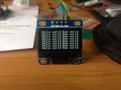
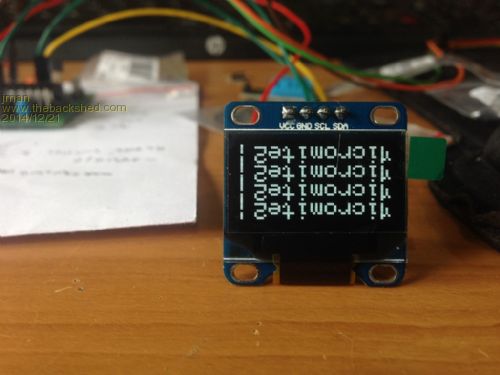
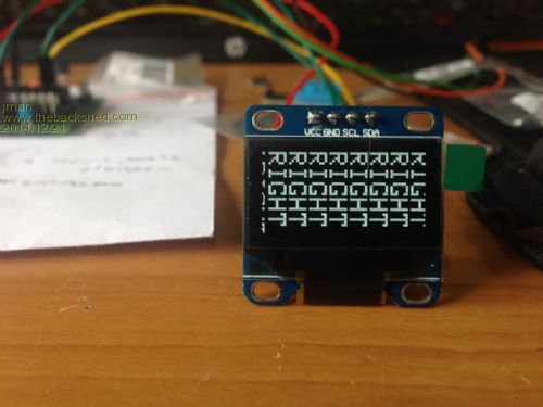
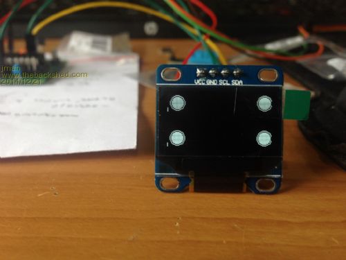
Regards Jman |
||||
| matherp Guru Joined: 11/12/2012 Location: United KingdomPosts: 11602 |
Jman There is an offset parameter to the init routine. It is probably set to 2 in the example program. This is needed for the 1.3" OLED displays as they seem to be wired differently. Change the offset to 0 and the problem should go away. |
||||
| matherp Guru Joined: 11/12/2012 Location: United KingdomPosts: 11602 |
Zonker What version of the firmware are you running? My code for the Nokia was tested on 4.6b27. I haven't retested on 4.6 release and can't now do this until Tuesday but I expect it work work fine. There were problems with SPI pre b27 which Geoff fixed for me that related to the mixed use of the SPI write and x=SPI(y) syntax in the same program. Peter |
||||
| Zonker Guru Joined: 18/08/2012 Location: United StatesPosts: 772 |
OK... I have updated to the new v4.6 firmware and all seems to be good..! Thanks Pete..! 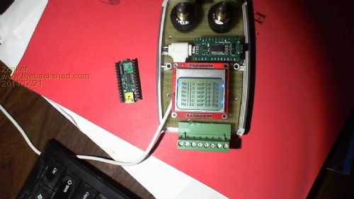
|
||||
| jman Guru Joined: 12/06/2011 Location: New ZealandPosts: 711 |
Thanks for that worked a treat Jmn |
||||
| matherp Guru Joined: 11/12/2012 Location: United KingdomPosts: 11602 |
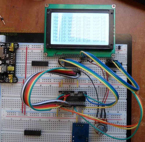
New file supporting standard KS0108 based GLCD. Note the use of DIL resistor packs to interface the 5V display to the MM Fixed pin allocation is: KS_RESET=14 'B05 KS_CS2=16 'B07 KS_CS1=15 'B06 KS_D7=26 'B15 KS_D6=25 'B14 KS_D5=24 'B13 KS_D4=23 'B12 KS_D3=7 'B03 KS_D2=6 'B02 KS_D1=5 'B01 KS_D0=4 'B00 KS_E=2 'A00 KS_RW=3 'A01 KS_RS=9 'A02 Use the Port/pin to map pin numbers to a 44-pin micromite if required 2014-12-30_200136_KS0108.zip |
||||
| matherp Guru Joined: 11/12/2012 Location: United KingdomPosts: 11602 |
New version for ST7781 controller used on many 2.4" TFT displays (controller reports ID 7753) 2014-12-31_103644_T24BAS.zip This version is only marginally slower but avoids using the Comm1 and I2C pins (I'm afraid the SPI pins are still used). the pin allocation is now: T24_CS=2 'a0 T24_CD=3 'a1 (marked LCD_RS on the board) T24_WR=9 'a2 T24_RD=10 'a3 T24_RESET= 14 'b5 T24_D0=4' b0 T24_D1=5' b1 T24_D2=6' b2 T24_D3=7' b3 T24_D4=23' b12 T24_D5=24' b13 T24_D6=25' b14 T24_D7=26' b15 Some things to note - this version does not work with the SPDF5408 based 2.4" displays. I've got one on order and will try and get this working when it arrives. Also, please note the use of the resistive touch display is not supported. The touch displays have a resistance of around 300ohm and when "touched" this can reduce further. Based on ohms law this means even untouched at 3.3V they pull 11mA. This is at the very maximum the driving capability of the PIC32MX and causes the drive voltage to sag leading to inaccurate results. I'm going to try using a buffer chip for the drive and will report results in a new thread. 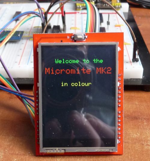
|
||||
| matherp Guru Joined: 11/12/2012 Location: United KingdomPosts: 11602 |
There are both 2.4" and 2.8" displays on sale that advertise they use the spfd5408 controller. Based on a sample of two, my 2.8" display and bigmik's 2.4" display, these actually use the ILI9341 or ILI9340 controller. This code works for both. There are also ILI9341 displays advertised but these use an SPI I/F. These are not supported by this version. Fixed pin allocation is: I9341_CS=2 'a0 I9341_RS=3 'a1 I9341_WR=9 'a2 I9341_RD=10 'a3 I9341_RESET= 14 'b5 I9341_D0=4' b0 I9341_D1=5' b1 I9341_D2=6' b2 I9341_D3=7' b3 I9341_D4=23' b12 I9341_D5=24' b13 I9341_D6=25' b14 I9341_D7=26' b15 Use the Port/pin to map pin numbers to a 44-pin micromite if required 2015-01-02_085904_ILI9341.zip 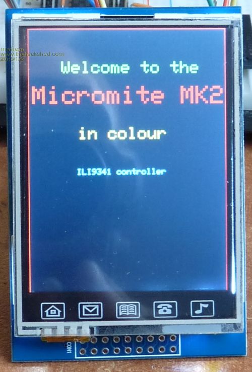
|
||||
| jman Guru Joined: 12/06/2011 Location: New ZealandPosts: 711 |
Silly question why not just add a series resistor Jman |
||||
| plasma Guru Joined: 08/04/2012 Location: GermanyPosts: 437 |
great Matherp ! thx a lot |
||||
bigmik Guru Joined: 20/06/2011 Location: AustraliaPosts: 2981 |
Fantastic Matherp, All, I now have my eBay $7 module working thanks to Peter's persistence. It is a bit unfortunate that it requires 13 pins to operate this particular module (ignoring the touch screen requirements) but at least the I2C pins are now clear.. I was talking to Peter about making a PCB that has a 'mite on it to drive this module and accept commands via I2C from a `master' mite.. but he has drawn my attention to another SPI based module that I feel would kill this particular one as it only requires 4 I/O pins (I dont know what the 4th pin is for unless it is a reset). This module is similarly priced and I can tell you the demo Peter has written is VERY impressive.. well worth spending $7 just to see it going through its paces. Well Done Peter.. 
Regards, Mick Mick's uMite Stuff can be found >>> HERE (Kindly hosted by Dontronics) <<< |
||||
| retepsnikrep Senior Member Joined: 31/12/2007 Location: United KingdomPosts: 134 |
Linky? Gen1 Honda Insights. |
||||
| bigmik Guru Joined: 20/06/2011 Location: AustraliaPosts: 2981 |
Without stepping on Matherp`s toes, assuming he comes up with a software solution fr the SPI modules A possible unit is this one, eBay link Regards, Mick Mick's uMite Stuff can be found >>> HERE (Kindly hosted by Dontronics) <<< |
||||
| matherp Guru Joined: 11/12/2012 Location: United KingdomPosts: 11602 |
The work I've done on the ILI9341 SPI display to reduce code size is portable to all the other displays, both monochrome and colour. If you let me know any you are actually using I'll prioritise updating these and posting them in this thread. The actual work updating the code is pretty trivial but setting up the display on the breadboard to test it is what takes the significant time  |
||||
| jman Guru Joined: 12/06/2011 Location: New ZealandPosts: 711 |
Hi I wondering if the I2C code could be adapted for this OLED OLED It uses a 96x16 OLED with a SSD1306 - I2C controller This the code I used OLED.pstring(5, 32, "Hello", 1, 0) OLED.pstring(5, 48, "Hello", 2, 0) I have tried and it does work to a degree with font size 1 the display is perfect with font size 0 it is broken up 96x16 OLED 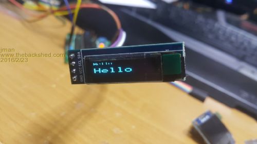
128x64 OLED 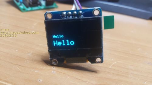
Many Thanks Jman |
||||
| Page 1 of 2 |
|||||
| The Back Shed's forum code is written, and hosted, in Australia. | © JAQ Software 2026 |
