
|
|
Forum Index : Microcontroller and PC projects : Battery Powered uMites
| Author | Message | ||||
| viscomjim Guru Joined: 08/01/2014 Location: United StatesPosts: 925 |
I am getting ready to start designing a project that would be nice to run on batteries. Googlizing finds many different types of batteries and techniques for this type of work. I am curious to see if any forum members have put together any battery operated devices using the uMite or other micros. I am considering 4 AA batteries with a 1702 type regulator, but this itself may draw too much power just sitting even if the uMite is sleeping. The other method being considered is the lipo type batteries but these can put out upwards of 4.2 volts charged, even though they are listed at 3.7v. Even that is too much for the uMite but not enough for a LDO regulator. This particular project will only be active once a momentary push button is pressed, so I was thinking that maybe the switch could initially power up the circuit and then the uMite could turn on a mosfet that supplies power to itself and the rest of the circuit, even though the switch is no longer pressed. When it is done doing its thing, the uMite could turn off the mosfet and shut itself down until the next button press that supplies the initial power to the uMite until it can take over with the mosfet. This will probably work well for this type of situation, but when there is no push button to start, the uMite will be running always, sleeping most of the time but still powered all the time. Any ideas would be wonderful to help make some battery run projects with a decent battery life. Thanks again!!!!! |
||||
Grogster Admin Group Joined: 31/12/2012 Location: New ZealandPosts: 9975 |
Hi Jim. 
I use the Micromite with battery power, and it is superb - especially with it's low sleeping current. In my case, I am using 9v rechargeable batteries, which feed an MCP1703-33 LDO regulator, which feeds the Micromite. With about 9v in, 3v3 out, there is 5v7 of headway, which keeps the circuit running fine for days on end, even on battery power. I posted a thread about waking a Micromite, and this may well help you with respect to waking up a sleeping chip when your button is pressed, or a timeout happens. I will find the link to that thread now..... EDIT: Here is the thread. This deals with my need to be able to sleep the Micromite to save power, but have EITHER a button wake it up, OR it wake itself every 30-45 seconds to check the battery. Upon self-waking, if the battery is OK, it just goes back to sleep again. Using the likes of a 1703-33, the quiescent(standby) current of these regulators is only 2uA(yes - 2 microamps!). So coupled with the uM's sleep current of 80uA or so, this makes a total standby current of around 82uA. If you plug that into an online battery life calculator, you can establish the estimated life of the battery. Using the above example, and a 250mA/h 9v rechargeable battery, the estimated life in standby is 2134 hours, or 88 days before the battery goes flat. Now, this is all in theory, mind. There will be differences such as if the uM wakes up(like in my case) to do ANYTHING, this will increase the current consumption, and alter that standby figure, but you can see how this all comes together. Please also note the warning about sleeping the uM on page 36. You need to make sure that no I/O pin is sourcing or sinking current before you sleep her, or she will continue to source or sink that current and that will drastically affect your standby current and battery life. Smoke makes things work. When the smoke gets out, it stops! |
||||
TassyJim Guru Joined: 07/08/2011 Location: AustraliaPosts: 6538 |
I have a project that has similar problems. In this case, power will be 'borrowed' from a 12V solar powered gate opener and I don't want to draw power continually for a twice-a-day, one minute task. I will be using an opto-isolator in the power supply line to turn on the regulator(s) and micromite. The micromite will turn on another transistor to hold the power on until all processing is completed then shut itself down. Jim VK7JH MMedit |
||||
| viscomjim Guru Joined: 08/01/2014 Location: United StatesPosts: 925 |
@Grogster, that is great information. I too was thinking about the 9v rechargeable as some come as li ion like these with 600mah. Very cool for a small form factor. I did not realize the ldo reg. has such a small standby current. Will start to play with this setup. I will need to play with the uMite's sleep mode. Thanks for the great info. @TassyJim, I like this idea when something external can fire up the uMite and then it can take over and shut itself off. This will more than likely be the way I will try since I have a push button in this circuit. Has anyone tried to implement any of the 3.7 volt batteries that are available? TBS to the rescue AGAIN! Thanks! |
||||
| plasma Guru Joined: 08/04/2012 Location: GermanyPosts: 437 |
i use : http://www.photobatterie.de/lithium-thionylchlorid-batterie- 3-6-volt.php for a bite indicator ( switch / low current led ) , it works fine since years . not tested with pic but i think this will work. |
||||
| Grogster Admin Group Joined: 31/12/2012 Location: New ZealandPosts: 9975 |
Clickable link for batteries linked to by plasma. The only issue, really, with the plethora of 3.7v batteries, is regulator overhead. Even the 1703's have a 200mV dropout voltage, meaning that you have to feed them 3.5v as a minimum to make them work, which only leaves you with a 200mV headroom to play with, which is not really very much. You could, naturally, run two of those batteries in series to give you 7.4v - that would be quite acceptable, IMHO, as a source of battery power. For me, size too was an issue, and after looking into all sorts of batteries, including those Li-ION packs you can get with the charger circuit embedded in them, and NiCd ones designed for old-style PC BIOS backup, I settled on the rechargeable 9v flavours mainly due to cost and availability. A stack of two or threee 3v lithium button cells may also work for you, provided the current consumption was kept to a minimum. Sucking currents of 20mA or more from a button cell will flatten it pretty quick. The 9v rechargeable batteries have the advantage that they can handle short duration current burst loads without to much effort, and being rechargeable, they can be fitted permanently inside a product. I use those PCB mount 9v battery holders you can get from Jaycar for about $1 each. Smoke makes things work. When the smoke gets out, it stops! |
||||
BobD Guru Joined: 07/12/2011 Location: AustraliaPosts: 935 |
If the load is light and intermittent then a couple of lithium AA batteries may do the job. In series it would give you 3.0 volts which is enough to run a PIC32MX170. |
||||
halldave Senior Member Joined: 04/05/2014 Location: AustraliaPosts: 121 |
I was wondering if the uMite could be powered off those cheap solar panels that come with those $2 solar lights, they have 2 AA rechargeable batteries that drive a led for up to 6hours overnight |
||||
| BobD Guru Joined: 07/12/2011 Location: AustraliaPosts: 935 |
The voltage may be too low with that setup. Two NiMH batteries gives 2.4 volts which is very close to the minimum of 2.3 volts for the PIC32. The idea of solar is good. Two solar panels in series charging 4 batteries to 4.8 volts (more while charging) combined with a 3.3 volt regulator may do the trick. |
||||
| halldave Senior Member Joined: 04/05/2014 Location: AustraliaPosts: 121 |
Certainly worth wiring two up in series... and having a play |
||||
| viscomjim Guru Joined: 08/01/2014 Location: United StatesPosts: 925 |
On this same approach of using a mosfet to power the circuit once a switch is pushed to "start" the circuit and then the uMite turns itself off basically, has anyone had any good experiences with the "logic level" fets that work on 3.3v instead of the 5v. There doesn't seem to be many options when it comes to a 3.3v logic level fet that I can find anyway. Any ideas or experiences? EDIT... This is what I'm thinking... The switch get pressed and the uMite gets powered on at which time the uMite turns on the mosfet and keeps it on until it is done doing it's thing and then turns it off. I am switching the ground, and am not sure if this is ok. The second thing is that the mosfet needs to be able to switch about 1 amp max which is why I am not using just a little transistor. The rest of the circuit is not shown, but there will be just a bit of current draw when the mosfet is on. 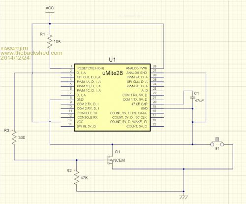
The mosfet right now is the irfz44n or this one. EDIT2... I guess I could also switch the high side also using a small relay quite easily, but solid state is cooler... I haven't found any p channel mosfets that work with 3.3v. |
||||
| Grogster Admin Group Joined: 31/12/2012 Location: New ZealandPosts: 9975 |
Merry Christmas. 
I still don't understand your use of the MOSFET as your uM switch, vs the predicted load of 1A. For switching on the uM(if using sleep and a 80uA or so sleeping current is not acceptable and you want ZERO off current), you could just use the transistor you mentioned - that would be how I would do it, if I was doing what you are doing. Transistor to keep the uM awake once the button was pressed, then the uM can switch the transistor off when it was finished and power itself down as you are already suggesting be done. I would then move the MOSFET to another I/O pin on the uM, and have the code switch that, to use the MOSFET to switch your higher current - there appears to be plenty of spare pins...
EDIT: This is how I would be inclined to do things: 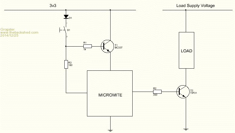
Using a couple of cheap NPN transistors. You COULD use MOSFET's, if you could find some 3v3 ones. I'm afraid that MOSFET's are not really my field - I was trained in the bi-polar transistor era! 
Anyway, using an NPN signal transistor as an emitter-follower to power the uM - that works fine for the low current the uM sucks when running, and although there is a voltage drop across the transistor, it is still within the power supply voltage requirements of the PIC32 chip. The TIP31 output switching transistor is wired as a common-emitter with the load in the collector circuit. There should be ZERO current consumption, until you actually press the switch. When you do, this powers up the uM, and one of the first things it does, is set an I/O pin high to hold T1 on, and this keeps the power on to the uM when the switch has been released. The 180 ohm resistor protects the uM from current, and D1 prevents the uM from sending voltage back onto the supply line once the button is released. All that is just a quick drawing, and not tested at all, but it should work. I could build it later to test this idea if you like. Smoke makes things work. When the smoke gets out, it stops! |
||||
| viscomjim Guru Joined: 08/01/2014 Location: United StatesPosts: 925 |
Grogster, first off, Merry Christmas to you also!!! I hope you are having a good one. I like your idea and will go over it my head for a bit. The "load" is also using the 3.3v supply but I think your circuit will still do the trick. If you have the parts available, a test would be very much appreciated if time permits. Could T1 be something like a 2n2222 type of transistor? Thanks for your time on this! EDIT... Since the rest of what is on this circuit is also 3.3v operation, maybe this could work... 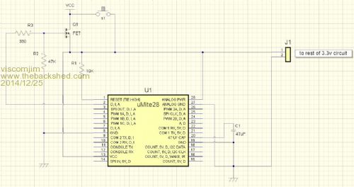
|
||||
| TassyJim Guru Joined: 07/08/2011 Location: AustraliaPosts: 6538 |
The base of T1 has to be 0.6V (approx) above the emitter for it to turn on. Not easy to do when you are supplying the base via the emitter. I would use a PNP transistor and using an open collector output from the uM to hold it on. In my case, I want to switch the regulators as well so I will be going with an opto-isolator. Easier to level-shift and I need them anyway for isolation. Jim PS Ho Ho Ho etc... VK7JH MMedit |
||||
| Grogster Admin Group Joined: 31/12/2012 Location: New ZealandPosts: 9975 |
@ viscomjim - I don't know the specs of that transistor. Generally speaking, more gain is a good thing with trasistors. Something important to remember about transistors: they are NOT switches, they are current amplifiers - IE: The current flowing in the collector-emitter circuit is proportional to the current flowing in the base-emitter circuit(for NPN). It is VERY common for people to confuse a transistor with a switch. If your load runs from 3v3 too, then you might have to go back to MOSFET output driver instead of the NPN TIP31 transistor, as the voltage drop across the transistor could prove a problem with a 3v3 supply and some reasonable current. Is your 3v3 load on all the time, or is it switched on and off with the uM? Absoueltely right - well spotted.  I was on my way out the door to my brother's place for family Christmas dinner, and so the drawing was right from my head, and not tested at all. I also agree with the PNP idea. I was on my way out the door to my brother's place for family Christmas dinner, and so the drawing was right from my head, and not tested at all. I also agree with the PNP idea.Smoke makes things work. When the smoke gets out, it stops! |
||||
| viscomjim Guru Joined: 08/01/2014 Location: United StatesPosts: 925 |
After doing a bit of research, I think I found a decent way to do this using 2 resistors, a P channel fet and a common npn transistor. Thoughts??? 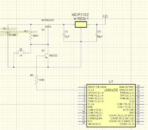
|
||||
jman Guru Joined: 12/06/2011 Location: New ZealandPosts: 711 |
Hi I have used the RFP30N06LE and the BUK9575-110a Logic level Fets with great success both these devices have a max gate threshold voltage of 2volts so no worries with 3.3v to turn them fully on. 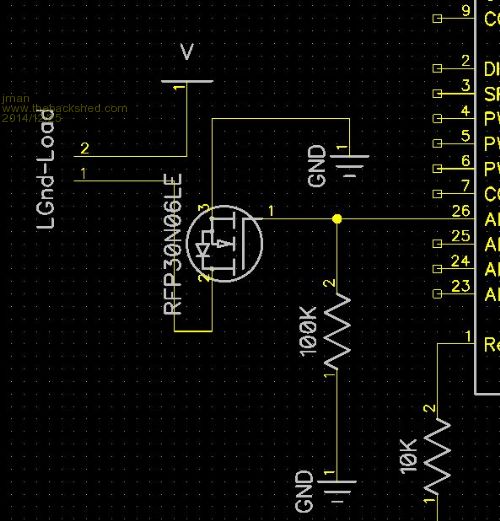
Regards Jman |
||||
| The Back Shed's forum code is written, and hosted, in Australia. | © JAQ Software 2026 |
