
|
|
Forum Index : Microcontroller and PC projects : Help - Programming ASCII Terminal
| Page 1 of 2 |
|||||
| Author | Message | ||||
| vk2sja Newbie Joined: 07/06/2013 Location: AustraliaPosts: 26 |
Hi All, Looks I'm in need of some help getting the firmware into my ASCII Terminal. Complete background: ASCII Terminal PCB purchased from Silicon Chip. Board labelled ASCII Terminal 24107141. I'm trying to use a PIC32 MX150F128B. Rather than the MX250 specified for this device. Simply because I only had the MX150 on hand. And I don't need USB for this particular application. A few posts ago I asked about this and the general consensus seemed to be that a MX150 would function so long as I didn't require USB OTG. I'm trying to program the chip with the Raspberry Pi programmer software 2014-09-08_164736_rpipic32.zip written by JohnS (thanks John!!). Available from here:- http://www.thebackshed.com/forum/forum_posts.asp?TID=6477&KW =simplest+32MX&PN=0&TPN=37 Why? Because Windows PC's are a little hard to come by round here. Because I don't have USB with the MX150 and I have no other programmer available. But I do have several Raspberry Pi's! :-) I am powering the ASCII terminal from a bench supply. The USB PWR jumper is *not* jumpered. The BOOTLOAD jumper is *not* jumpered (but in desperation I did try this - no change). Interconnections between Rpi and ASCII Terminal ICSP connector as per JohnS howrpi.txt document. Using the "identify" command option all I get is:- $sudo ./rpipic32 -i setting MCLR HI MCLR LO MCHP sent DATA_IOCODE -> 0x00001000 Inconsistent data - check wiring Unknown DEVICE ID - Disconnected? Exiting The actual hex code for the DATA_IOCODE is different each time it is run. And so it looks like random noise to me. I'm concerned that the bench supply is only showing a current draw of about 5mA. This rises to 20mA if I jumper the BOOTLOAD jumper which turns on the LED. This current draw seems awful low to me and so I went looking for the 8Mhz clock signal. With x10 scope probe direct to the crystal (tried both sides) all I can see is 50hz power line noise. Crystal is full sized HC-49 which tested all right in a test oscillator. So for the moment I'm out of ideas. So over to the collective brains trust. Any and all advice gratefully received. Steve. |
||||
| MicroBlocks Guru Joined: 12/05/2012 Location: ThailandPosts: 2209 |
I think the crystal is difficult to check with an un-programmed chip. It will run on its internal oscillator and while programming the programmer gives the data and clock. 1) Can you take the chip out of the board and put it in a breadboard or maybe a ZIF socket and program it directly? You would need only one capacitor and resistor. After that check if it works on the PCB. If not 2) Touch up every solder joint. Make sure the capacitor between VCap and ground is the right version (X5R multilayer or tantalum, value >=10uF) and that its connection is good. Maybe swap it for another. Retest if the oscillator is running. Microblocks. Build with logic. |
||||
| vk2sja Newbie Joined: 07/06/2013 Location: AustraliaPosts: 26 |
Alright, at the risk of partially answering my own question we have made some progress. The ICSP pins used between MX150 and MX250 appear to be different. Using information found here (Google): http://www.users.on.net/~tassyjim/stuff/MuP%20Manual.pdf (See Jim, You answer questions even when your not around!  ) )
I tack-soldered some resistor leads to pins 4 and 5 of the MX150 and connected the Rpi programmer GPIO7 to pin 4 and GPIO8 pin 5. Now when I do:- $sudo ./rpipic32 -i setting MCLR HI MCLR LO MCHP sent DATA_IOCODE -> 0x14d06053 PIC32MX150F128B RAM 0 8000, ROM 1D000000 20000, BOOT 1FC00000 C00 DEVID Version (chip Revision) 1 So I program the device with the original firmware because it also contains the boot loader (leaving version 1.2 aside for the moment) with:- $sudo ./rpipic32 -e -v Terminal_V1.0+plus_Bootloader.hex <snip lots left out> 90% . PE_Read 1fc00000 -> 10000 (read) -> 401a6000 PE_Read 1d000000 -> 10000 (read) -> ffffffff $ No obvious errors. It looks like a good load. If I run the same command again the hex values above are consistent. Sadly however if I disconnect the Rpi programmer and power cycle the ASCII Terminal I get nothing on my VGA screen (Yes, I did remember to solder the green jumper - only just). 
So again I cry - Help! I could be doing something silly still (very likely). But it begins to look like this firmware does not want to "fly" with my MX150. Perhaps the person reporting that the firmware works with a MX150 was using a breadboard circuit rather than the official (Silicon Chip) PCB. And there are other circuit changes other than ISCP that need to be done?? Again, all suggestions gratefully received. Steve. |
||||
| Geoffg Guru Joined: 06/06/2011 Location: AustraliaPosts: 3362 |
1. Make sure that the VGA monitor is properly plugged in when you power on the board otherwise the firmware will generate composite output. 2. Jumper the serial Tx and Rx pins so that anything that you type on the keyboard will be echoed to the video output. 3. If you have an oscilloscope check that you have the correct signals on the VGA connector. Geoff Geoff Graham - http://geoffg.net |
||||
| vk2sja Newbie Joined: 07/06/2013 Location: AustraliaPosts: 26 |
Hi TZ, Yes I think your right. After my "successful flash" above I can see the external 8Mhz clock signal with the scope. So something happened. Done. Two different monitors. No video out. Monitors can "see" that I have connected to a device (they stop complaining about the VGA cable being unplugged) but fail to sync or see any video signal. They go into power-save mode shortly thereafter. Installed jumper between RX and TX pins on serial port. No echo. Blank screen. Are CAPS-LOCK and NUM-LOCK supposed to come on and toggle On/Off? Because I'm not seeing that either. Can do. Will have to do a crash course on what the signals are supposed to look like. An after-diner research project and a tomorrow job. I went through all the pinout differences between the MX150 and the MX250. The only one that I could see that might be an issue is the MX250 pin 23 VUSB3v3. Which on the MX150 is a data pin RB12. So I carefully bent the pin up and out so as it floats when the chip is plugged into the socket. All other pins look correct or benign. I don't want to modify the board as I will be ordering a MX250. Just that I'd like to 'play' during the break and this is the only chip I had on hand. Thanks TZ/Geoff. Steve. |
||||
| Geoffg Guru Joined: 06/06/2011 Location: AustraliaPosts: 3362 |
OK, I just tested a MX150 in the original prototype, programmed it with Terminal_V1.0_plus_Bootloader.hex from the Construction Pack and it worked perfectly (without USB). So, you don't need to be worried about Vusb3v3. > Are CAPS-LOCK and NUM-LOCK supposed to come on and toggle On/Off? Yes. Do you get the LED illuminated on the Terminal PCB? If yes, the firmware is running OK, if not there is something stopping the microcontroller from running. > Will have to do a crash course on what the signals are supposed to look like. I use this website as my reference for VGA timing (the VT100 Terminal generates IBM 640x480 60Hz signals). > The ICSP pins used between MX150 and MX250 appear to be different. No, they are the same. You need to have the baud rate jumpers removed when programming the chip in circuit. This is because the baud rate jumpers short some programming pins to ground. This could account for your programming problem. Geoff Geoff Graham - http://geoffg.net |
||||
bigmik Guru Joined: 20/06/2011 Location: AustraliaPosts: 2981 |
Hi Steve, Firstly what version VT HEX are you trying to flash into the PIC? I remember (and I fell for this myself) that ver 1.0 has a bug of some sort in PAL mode and VGA (no display with USB plugged up or some thing else forgot the details) With no USB you will not be able to upgrade the firmware to 1.2 (I think that is the latest). I dont believe that Geoff actually released a version of 1.2 that came with the bootloader built in so I programme mine with this HEX file that is one I saved from a chip that I burned 1.0 into and then updated via USB.. I am fairly certain that it is a fully working including bootloader but until a new version is realeased I cannot test that part. 2014-12-26_084030_VT_1.2.zip Secondly I have a programming jig I made from an old MuP Ver 1 PCB fitted with a ZIF socket and I can guarantee that both the 150 and the 250 have the same ICSP pins for flashing, no need to change anything there. Geoff, You intimated some time ago that you would release a V1.2 with bootlader firmware.. Did you ever get around to that one? Regards, Mick NOTE that I dont think that you can flash 1.2 (as available off geoff's site into the 150/250 without first flashing 1.0 then loading via the windows USB update programme. Try the HEX I supplied.. Mick Mick's uMite Stuff can be found >>> HERE (Kindly hosted by Dontronics) <<< |
||||
| vk2sja Newbie Joined: 07/06/2013 Location: AustraliaPosts: 26 |
Thanks Geoff! I'll return pin 23 (Vusb3v3) to its rightful position in the socket. Yes, I did have a baud rate jumper installed in position 'C' - dumb! I'll remove all the baud rate jumpers and try again using the on-board ICSP header. The only time I've ever seen LED1 illuminate is when I short the BOOTLOAD position with a jumper. So I guess that means 'No' the LED does not light. And therefore the firmware is not running. I've just tried it again. If I connect Clock and Data to pins 2 & 3 of the micro (either way round - tried both) as per the ASCII Video Terminal circuit and PCB layout, the programmer software is not able to talk to the chip. Previously when Clock and Data was connected to pins 4 and 5 (not sure which way-round as I type) the programmer software can see the chip and appears to work normally. Pins 4 & 5 appear to be the pins used in Mick's uMite PCB as per the document above. Confused. Just looked at the Datasheet again. Pins 4 & 5 are consistent between both MX250 and MX150 as PGED1 and PGEC1. But the ASCII board and circuit show the clock and data connected to pins 2 and 3 which are somewhat different between the two chips. Which pins are we supposed to be using? Below is the session log for what I "think" is a successful burn of the V1.0 software. When JohnS gets to reading this perhaps he can confirm that it looks correct. file Terminal_V1.0_plus_Bootloader.hex, erase 1
setting MCLR HI MCLR LO MCHP sent DATA_IDCODE -> 0x14d06053 PIC32MX150F128B RAM 0 8000, ROM 1d000000 20000, BOOT 1fc00000 c00 DEVID Version (chip Revision) 1 erasing... erased MCHP_STATUS -> 0x8a CPS CFGRDY FAEN step 1... 2... 3... 4... 5: load PE loader... 6... 7: load PE... 8 PE Version: 301 laddr 1d000000 laddr 1d010000 laddr 1fc00000 programming main flash: . . . . . . . . . . . . . . . . . . . . . . . . . . . . . . . . . . . . . . . . . . . . . . . . . . . . . . . . . . . . . . . . . . . . . . . . . . . . . . . . . . . . . . . . . . . . . . . . . . . . . . . . 10% . . . . . . . . . . . . . . . . . . . . . . . . . . . . . . . . . . . . . . . . . . . . . . . . . . . . . . . . . . . . . . . . . . . . . . . . . . . . . . . . . . . . . . . . . . . . . . . . . . . . . . 20% . . . . . . . . . . . . . . . . . . . . . . . . . . . . . . . . . . . . . . . . . . . . . . . . . . . . . . . . . . . . . . . . . . . . . . . . . . . . . . . . . . . . . . . . . . . . . . . . . . . . . . . 30% . . . . . . . . . . . . . . . . . . . . . . . . . . . . . . . . . . . . . . . . . . . . . . . . . . . . . . . . . . . . . . . . . . . . . . . . . . . . . . . . . . . . . . . . . . . . . . . . . . . . . . 40% . . . . . . . . . . . . . . . . . . . . . . . . . . . . . . . . . . . . . . . . . . . . . . . . . . . . . . . . . . . . . . . . . . . . . . . . . . . . . . . . . . . . . . . . . . . . . . . . . . . . . . 50% . . . . . . . . . . . . . . . . . . . . . . . . . . . . . . . . . . . . . . . . . . . . . . . . . . . . . . . . . . . . . . . . . . . . . . . . . . . . . . . . . . . . . . . . . . . . . . . . . . . . . . . 60% . . . . . . . . . . . . . . . . . . . . . . . . . . . . . . . . . . . . . . . . . . . . . . . . . . . . . . . . . . . . . . . . . . . . . . . . . . . . . . . . . . . . . . . . . . . . . . . . . . . . . . 70% . . . . . . . . . . . . . . . . . . . . . . . . . . . . . . . . . . . . . . . . . . . . . . . . . . . . . . . . . . . . . . . . . . . . . . . . . . . . . . . . . . . . . . . . . . . . . . . . . . . . . . 80% . . . . . . . . . . . . . . . . . . . . . . . . . . . . . . . . . . . . . . . . . . . . . . . . . . . . . . . . . . . . . . . . . . . . . . . . . . . . . . . . . . . . . . . . . . . . . . . . . . . . . . . 90% . . . . . . . . . . . . . . . . . . . . . . . . . . . . . . . . . . . . . . . . . . . . . . . . . . . . . . . . . . . . . . . . . . . . . . . . . . . . . . . . . . . . . . . . . . . . . . . . . . . . . programming boot flash: . . . . 10% . . 20% . . . 30% . . 40% . . 50% . . . 60% . . 70% . . 80% . . . 90% . PE_Read 1fc00000 -> 10000 (read) -> 401a6000 PE_Read 1d000000 -> 10000 (read) -> ffffffff |
||||
| vk2sja Newbie Joined: 07/06/2013 Location: AustraliaPosts: 26 |
Hi Mick, Thanks for the Version 1.2 with Bootloader. Much appreciated. All understood and Yes, I was trying v1.0 from the construction pack (which I think I read is actually v1.1). And 'yes' the reason I dropped back to this version was because I found that v1.2 had no bootloader. So I think that you are correct on all counts. I'll try flash your version tomorrow morning. It's getting dark and cold now and I've shut-down the Shack for the night. Still confused about the ICSP pins. The ASCII board uses (and circuit shows) pins 2 and 3 as PGED3 and PGEC3 which is not what your uMite looks to use. According to the circuit in the document above. Cheers Steve. |
||||
BobD Guru Joined: 07/12/2011 Location: AustraliaPosts: 935 |
Steve You sound confused about pins. Have a look at the image or look in the zip for a bigger picture. It is from the Microchip datasheet. 2014-12-26_100904_PIC32150F128B.zip 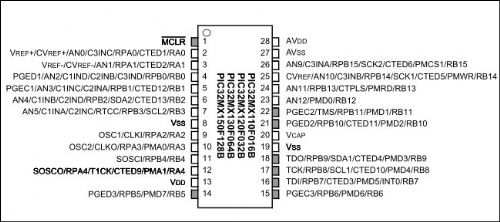
Bob |
||||
| vk2sja Newbie Joined: 07/06/2013 Location: AustraliaPosts: 26 |
Hi Bob, Thanks. I've got the data sheet pinouts. Been looking at them most of the afternoon. The confusion is that the ASCII terminal board connects ICSP data and clock to pins 2 & 3 (perhaps not in that order). While Mick's uMite has them connected to pins 4 & 5. And I'm being told that the ICSP clock and data are the same for both chips. But last time I checked 2 != 4 and 3 != 5 
So there is something here I don't understand. |
||||
| BobD Guru Joined: 07/12/2011 Location: AustraliaPosts: 935 |
Do you have a choice but to trust the data sheets? Diagrams have been known to be wrong before. |
||||
| BobD Guru Joined: 07/12/2011 Location: AustraliaPosts: 935 |
The pinouts for the 150F and the 250F are different. The 250F has the following PGED1=4 PGEC1=5 PGED2=21 PGEC2=22 PGED3=2 PGEC3=3 The 150F has the following PGED1=4 PGEC1=5 PGED2=21 PGEC2=22 |
||||
Grogster Admin Group Joined: 31/12/2012 Location: New ZealandPosts: 9975 |
Yes, as others are saying - it is only the pinout. I can see why that would throw you, though. So, in other words, you CANNOT put a 150 chip in the Silicon Chip PCB you have there and expect it to work, as that board was designed for the 250 chip, and the programming pins especially, are then not where the PICkit3 is expecting them to be if you use a 150 chip. 
However, you can design your own PCB around the 150(or just build it up on a breadboard for the purposes of testing) and that works, from all the information I have read. Smoke makes things work. When the smoke gets out, it stops! |
||||
| robert.rozee Guru Joined: 31/12/2012 Location: New ZealandPosts: 2528 |
bob just beat me to it. while an MX150 will work in the terminal PCB, the ICSP connector on the PCB runs to the wrong pins, so you can not upload firmware to the device. in all other regards (apart from USB) it works. it is allowable to use any of the three pairs of ICSP pins (PGCx and PGDx), but they must be used in pairs. ie, using PGC1 and PGD2 together will not work. your easiest bet is to make up a ZIF socket on a scrap of veroboard containing the ICSP socket (wired as per micromite) and the 10uF capacitor, and use that for programming devices. pairs 1 and 2 are on the same pins on both MX150/170 and MX250/270 devices. this is what i do. cheers, rob :-) 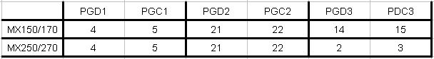 |
||||
| vk2sja Newbie Joined: 07/06/2013 Location: AustraliaPosts: 26 |
Thanks Bob, That sums it up succinctly I think. I've been reading:- http://ww1.microchip.com/downloads/en/DeviceDoc/61129F.pdf And from what I read it does not matter which PGEx pair you use. So long as you use a matched pair. The ASCII Terminal PCB connects the ICSP clock and data to the PGE3 pair on pins 2 & 3 of a 250F. Which is fine accept when you try and substitute a 150F which has no PGEx pair at all on pins 2 & 3. I'll mod the PCB to move the ICSP data & clock permanently to pins 4 & 5 -> PGE1. Which should work for both 250F and 150F and also solve the problem of needing to remove the baud rate jumpers prior to programming. However... Pin 5 PGEC1 on the ASCII terminal is connected to 3v3 via 100k + 10k resistor chain. As it is being used as the serial RX pin. I don't suppose this is causing me a programming issue? Software didn't error at all. And I would have thought being on the other side of 110k would have been alright. Anyway, things to try tomorrow. Cheers Steve. |
||||
| Geoffg Guru Joined: 06/06/2011 Location: AustraliaPosts: 3362 |
I programmed my test MX150 in a dedicated programmer (not in circuit) which explains why I did not hit the programming pins issue. You learn something new each day! The fact that LED1 does not illuminate is a sure indicator that the PIC32 CPU cannot start. Things to check: - The 10uF on pin 20 must be a high quality tantalum. Is the polarity correct? Try replacing it with a 47uF. - Check that 3.3V is on pins 23, 26 and 13. Check that ground is on pins 27, 8 and 19. With just the 10uF cap + power a correctly programmed chip should pull pin 14 low, which turns on the LED indicating that the firmware is running. No other connections are required. Geoff Geoff Graham - http://geoffg.net |
||||
| Geoffg Guru Joined: 06/06/2011 Location: AustraliaPosts: 3362 |
Sorry Mick, I forgot about that. I will give it a go ASAP. Geoff Geoff Graham - http://geoffg.net |
||||
| JohnS Guru Joined: 18/11/2011 Location: United KingdomPosts: 4335 |
Looks like it's programmed OK (in that longish debug output) but as has been pointed out the correctly programmed firmware isn't happy or else it's the wrong firmware. I've used any convenient pair of PGC/PGD and has always just worked so i think Mchp datasheet is correct on that issue. John |
||||
| vk2sja Newbie Joined: 07/06/2013 Location: AustraliaPosts: 26 |
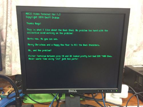
Eureka! As they say. Big thanks to:- JohnS, for writing the Raspberry Pi ICSP programming software. Works a treat and I can assure everyone that it is FAST! In my case especially important because I had no other programmer available. Bigmik, for thoughtfully providing an updated v1.2 firmware image that contains both the Bootloader and Program. Mind you when the MX250F arrives I'll still have to flash it with the Rpi because I have no USB with the MX150F. But at least I have the latest Firmware. BobD, and all the others who replied. For giving me a quick run-down on 23 bit PIC ICSP programming and pinouts. And Finally to Geoff, who was able to pin-point the problem to the 10uF Tantalum on pin 20. And the problem? My 10uF Tantalum capacitor shows an ESR of about 0.5K Ohms in my component tester. Whereas a garden variety 10uF electrolytic was reading about 0.2K Ohms in the same device. So I replaced it with a 1uF (all I had on hand) Tantalum that had ESR so low the tester couldn't even see it (i.e. less than 1 Ohm). As soon as I did this it burst into life. Wishing everyone a Happy and *Safe* New Year! Steve. |
||||
| Page 1 of 2 |
|||||
| The Back Shed's forum code is written, and hosted, in Australia. | © JAQ Software 2026 |
