
|
|
Forum Index : Microcontroller and PC projects : Decoding an LED display’s pins...
| Author | Message | ||||
Grogster Admin Group Joined: 31/12/2012 Location: New ZealandPosts: 9975 |
Hi folks. 
I have 20x 3-digit LED displays here that I would love to use for a project. Problem is, there is no datasheet for them, and I have not been able to get anywhere with my usual friend - Google. 
The only ID is inside the epoxy which reads: 5361-2A on the top-right of the display, looking at it from the rear. At the top-left, there is: JC, and pin-1 of the display is marked.(it is bottom-right of pins). The display has ten pins - 5 on the top, five on the bottom. It is obviously a multiplexed display, but I don't know if it is common-anode or common-cathode, and I have no idea which common is which pin, nor what pin is which segment. Does anyone know of any places I could look to perhaps find some data on these? I am also thinking of putting a MicroMite to work here, and connecting all ten pins to the Micromite(with loading resistors!), then by running some code where it steps through all the combinations one by one high then low with a button press, I can then write down on paper as the Micromite steps through, which pins result in which segments lighting. From that, I could decipher the pin arrangement, but someone else might have a better link or source? ...it could be an interesting use for a Micromite though!  Smoke makes things work. When the smoke gets out, it stops! |
||||
muddy0409 Senior Member Joined: 15/06/2011 Location: AustraliaPosts: 125 |
Just get a 1k resistor and 12v (or so) power supply, or battery. Make the resistor in series with one power lead. then just go around and touch any 2 pins until a LED lights. Leave one of the power leads connected and move the other one to other pins til you get a different LED to light. Just keep that up until you have gone around all pins, You will get a couple of connections where no LED lights, use this no led pin to move the first connection to and redo all the other pins again. A bit tedious but pretty easy when you get the general idea. Being a 3 digit display will give you 3 pins that light no leds. these 3 are the commons, either A or K depending on the display and the polarity of the wires connections. Hope that makes sense. Don't poo poo conspiracy theories. Remember that everything ever discovered started somewhere as a theory. |
||||
| Grogster Admin Group Joined: 31/12/2012 Location: New ZealandPosts: 9975 |
Good idea, and remarkably simple - not a MCU in sight. 
I will do this, and then post the results. Smoke makes things work. When the smoke gets out, it stops! |
||||
bigmik Guru Joined: 20/06/2011 Location: AustraliaPosts: 2981 |
Grogs, Try this pinout datasheet it seems to be a standard pinout Regards, Mick Mick's uMite Stuff can be found >>> HERE (Kindly hosted by Dontronics) <<< |
||||
| Grogster Admin Group Joined: 31/12/2012 Location: New ZealandPosts: 9975 |
@ Mick - two too many pins. That PDF is a 12-pin module, mine only has 10.
Here is what I have found so far: Display graphic: 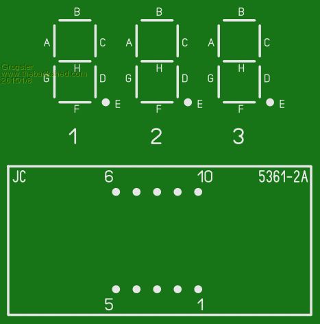
Pin probing chart: 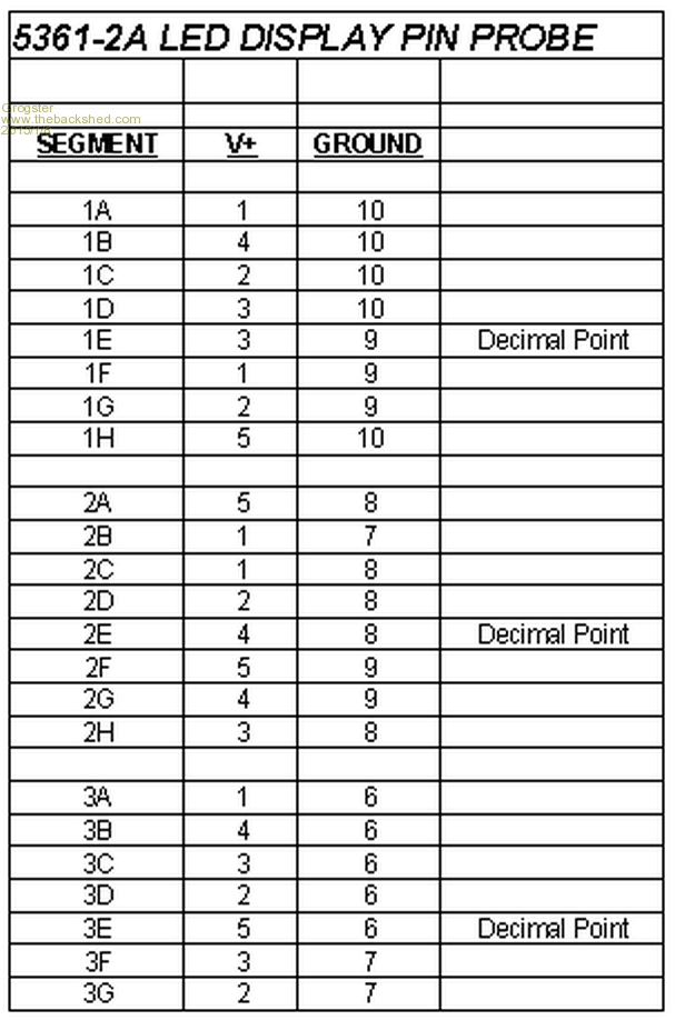
From what I can gather, is is therefore a common-cathode display, but interestingly, there seems to be five distinct groups of common connections instead of the more usual three(one for each digit). Can anyone here make more sense of this chart then me at this point? EDIT: I am now going to draw this chart as a schematic to see how things are set up behind the epoxy.
EDIT: Last line is missing from the chart. Segment 3H: V+=4, GND=7. Smoke makes things work. When the smoke gets out, it stops! |
||||
| bigmik Guru Joined: 20/06/2011 Location: AustraliaPosts: 2981 |
Grogs, Seems a weird arrangement... The one I sent us actually 11 pins.. There is no pin 6.. I can't find one that has 10 pins either... I will keep searching. Mick Mick's uMite Stuff can be found >>> HERE (Kindly hosted by Dontronics) <<< |
||||
| Grogster Admin Group Joined: 31/12/2012 Location: New ZealandPosts: 9975 |
Here is the schematic, drawn from my probing chart: 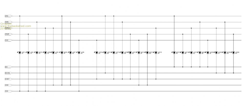
Me thinks this is a matrix LED display rather then a common-cathode. The same thing as a keypad matrix, but just a little little larger. No wonder I got them for about 50c each at the time! 
Still, now that I know how it is wired up, I could easily dedicate a $3 MicroMite chip to act as an I2C or serial driver.... EDIT: Image is a little fuzzy, so here is a link to the GIF file which will show it clearly. Smoke makes things work. When the smoke gets out, it stops! |
||||
| robert.rozee Guru Joined: 31/12/2012 Location: New ZealandPosts: 2528 |
looks like there are 24 segments, arranged in a 5x5 grid. the only combination not used is 5-7. working out how to drive it will be fun, but not too difficult. hint: for each digit (0-9) in each location (1-3) you'll need to store 25-bits, which will all nicely fit in a table of 30 integers on a mk2 micromite. rob :-) |
||||
| Grogster Admin Group Joined: 31/12/2012 Location: New ZealandPosts: 9975 |
I might need to call on your expertise, Rob - you seem to already know what I am going to have to do! 
EDIT: I reckon I could make it work, by connecting all ten pins to the MicroMite(with loading resistors in the anode side, for example), and use the PORT command in the same way as we talked to the LPT printer a few months back. I'd just use ten bits instead of eight. MM manual says you can use any number of pins up to the total available. I will hook one of these displays up to a MM tomorrow, and write some code for the purposes of experimentation. Smoke makes things work. When the smoke gets out, it stops! |
||||
| muddy0409 Senior Member Joined: 15/06/2011 Location: AustraliaPosts: 125 |
That would make sense, a matrix rather than CC or CA 3 digits. You just can't get 8 segments and 3 commons in 10 pins. Matrix would make it fairly simple to operate from an MCU, or even with one of the Maxim matrix drivers. Anyway, lotsa luck. Don't poo poo conspiracy theories. Remember that everything ever discovered started somewhere as a theory. |
||||
BobD Guru Joined: 07/12/2011 Location: AustraliaPosts: 935 |
Grogs Have a read of this and see if it fits with your display. I looked at it but at this time of the day my head hurts to look at it too hard. Bob |
||||
| bigmik Guru Joined: 20/06/2011 Location: AustraliaPosts: 2981 |
Grogster, Well Bu@@er me... That would have to be the weirdest (and probably most difficult thing to drive). To do it properly would `probably' mean that every segment is multiplexed rather than every digit.. I would toss them in the back of the drawer and buy more standard types.. But I know you love `PAIN'.. When I was looking around I saw someone on eBay have the 11 pin variety for 10 pcs for $8 or so.. Regards, Mick Mick's uMite Stuff can be found >>> HERE (Kindly hosted by Dontronics) <<< |
||||
| Grogster Admin Group Joined: 31/12/2012 Location: New ZealandPosts: 9975 |
I am guessing that there is a reason for designing a display like this - they must exist for a reason, and I do remember reading theory on LED matracies, so I guess it is perhaps just a case of what was cheapest at the time. Explains why I got them so cheap - 50c each for a three-digit red LED display seemed like a bargain - at the time!
I just assumed they would be a standard common-cathode or common-anode display, without looking to much at the pin count at the time. I won't bin them just yet - I want to see if I can decipher how to drive them - I already have a plan I want to try, just to light one number on one segment first. For the purposes of this threads' information, I will post back with the results in due course. Smoke makes things work. When the smoke gets out, it stops! |
||||
| Grogster Admin Group Joined: 31/12/2012 Location: New ZealandPosts: 9975 |
I give up.  
While I WAS able to get some kind of response from these things, it is too hard to keep the flippin' numbers on the display - the rest of the code keeps slowing things down(generating LED flicker), which is to be expected really. 
I'm not a big fan of non-standard arrangement anyway, but thought it was worth a try. I have ordered some of these instead. These are common-cathode, and you can see by looking through the epoxy on the back, that they appear to be the standard arrangement. I have bought just one batch of these (5 displays), to check first, and if they are the standard arrangement, I can get more. I really liked the 50c matrix ones I have, as they came with a cute little bezel for panel mounting, and they looked great in that. The replacements above are the same 0.56" size, so I am HOPING that I can swap one for the other, and keep the panel bezels. Smoke makes things work. When the smoke gets out, it stops! |
||||
| The Back Shed's forum code is written, and hosted, in Australia. | © JAQ Software 2026 |
