
|
|
Forum Index : Microcontroller and PC projects : grage door indicator
| Page 1 of 2 |
|||||
| Author | Message | ||||
BobD Guru Joined: 07/12/2011 Location: AustraliaPosts: 935 |
I recently moved to a new house. I need to be able to remotely see the whether the garage roller door is open or not. The door controller doesn't have this capability. The distance is not great, just through a wall. I was thinking that a couple of LEDs would do the trick. One for full up and another for full down. Then I got to thinking (dangerous, lol) about what happens if the door is stopped at some intermediate point. One thing I need is a reliable means of sensing the door's location. I thought about magnetic reed switches but the door is steel and the tracks are steel. Not a great environment for magnetic sensing. So there's the two things I need: What to use for sensing Ideas for showing partial opening. The neatest correct answer gets a smiley or three.  |
||||
bigmik Guru Joined: 20/06/2011 Location: AustraliaPosts: 2981 |
BoB, You could always mount one of those distance measurement sensors to your door and measure the exact distance from the floor. But really You only really care if the Door is NOT closed dont you? Why worry knowing exactly where it is. My garage door (is alarmed) but it uses a magnetic sensor (reed maybe) bolted to the floor that triggers when the magnet (bolted to the door) comes in proximity to the switch. That is all you need, no smarts just a power source and an LED mounted where you can see if it is closed. Regards, Mick PS these floor mounted sensors are rugged, a car could drive over them. I will try to find a photo of one (or take a photo) Mik Mick's uMite Stuff can be found >>> HERE (Kindly hosted by Dontronics) <<< |
||||
TassyJim Guru Joined: 07/08/2011 Location: AustraliaPosts: 6538 |
I would go with the reed switches and a magnet mounted on the door. If needed, the magnet can be fitted to an aluminum bracket attached to the door and similar for the switches but I don't think the steel will be much of a problem. I bought a few cheap magnet/switch sets from ebay recently. Just have to get around to fitting them. The roller doors were one spot as well at the front gate. The magnets usually work about 20mm from the reed switch. Jim VK7JH MMedit |
||||
| bigmik Guru Joined: 20/06/2011 Location: AustraliaPosts: 2981 |
Bob, This is the type of reed switch my garage door has. eBay Link My magnet was a bit different and was mounted on a 3mm thick Aluminium bracket but the floor mounted Reed switch with flexible braided tube to protect the wires looks more or less the same. Mick Mick's uMite Stuff can be found >>> HERE (Kindly hosted by Dontronics) <<< |
||||
| BobD Guru Joined: 07/12/2011 Location: AustraliaPosts: 935 |
Mick and Jim, thanks for that info. I'll look into it and get back. Bob |
||||
| MicroBlocks Guru Joined: 12/05/2012 Location: ThailandPosts: 2209 |
I would attach those on the top of the door. No problems with driving over it or it getting wet. Microblocks. Build with logic. |
||||
brucepython Regular Member Joined: 19/06/2011 Location: AustraliaPosts: 64 |
I've tried several sensor possibilities and found that optical was not the way to go due to the horrid state of my garage floor, resulting mainly to the combination of a gravel driveway, winds that blow rubbish inside and my bad memory when it comes to closing the door (which was why the indicator was required). Spiders don't help much either. In my junk box I found an old microswitch with a long spring steel actuator attached. This fits through a rectangular slot that happened to be at the bottom of the door guide and, with a bit of movement allowed in the mounting block, can be adjusted to work reliably. It's been there for years and hasn't failed yet.  
Bruce |
||||
| bigmik Guru Joined: 20/06/2011 Location: AustraliaPosts: 2981 |
TZ, Bob, The switch I suggested is designed to be floor mounted and strong enough to be driven over by a truck it is also fitted with a flexible (like some maggy lamps) sheath that houses the wires to prevent water damage. Besides you mount it literally the first 100mm into the garage opening, if your drive that close to the door you should consider either a smaller car or a bigger garage openeng. 
Regards, Mick Mick's uMite Stuff can be found >>> HERE (Kindly hosted by Dontronics) <<< |
||||
| Gordz Regular Member Joined: 10/08/2013 Location: AustraliaPosts: 55 |
A cheap ultrasonic ranging module ( 4 or 5 bucks on Ebay) would give an accurate indication to the nearest 5mm or so if mounted on the door slider. Or an absolute quadrature encoder sensor if you don't want to use ultra sonics. |
||||
| WhiteWizzard Guru Joined: 05/04/2013 Location: United KingdomPosts: 2991 |
Hi Bob, Re-visiting my logistics days, we would often need to open a loading-bay door to a certain position depending upon the size of the vehicle backed onto the loading bay (the idea being to minimise cold air coming into the warehouse on cold days/nights). Being head of innovation I tried various techniques - however all included a heavy duty magnetic sensor to determine when fully closed. As mentioned, these sensors needed to be heavy duty able to withstand forklift trucks being driven over them (and people standing on them). For your requirement I would definitely use one of these, but only as part of the solution - in fact use two (one either side) if you need 100% reliability. To compliment the above heavy duty sensor, to determine opening position, there were two methods we preferred to adopt. One was to use a magnet mounted on the side of the door (roller blind) and then use the necessary number of reed switches on the loading bay side to allow the controlling electronics to dictate when to cut power (and hence have the required opening position). I would also have a reed switch at the fully open position rather than let the door's electronics cut the power (they do this by measuring a sudden increases in motor current being drawn). So if I needed three custom opening positions (as well as fully open), I would use one magnet and four side sensors, and one heavy duty mag/sensor. The other method that worked well was to add a rotary sensor onto the roller blind shaft/motor mechanism. This would still require the heavy duty sensor to detect when fully closed, and in your case I would add a side magnet and a side sensor to detect fully open. Then you can auto calibrate the rotary decoder values which when using a MicroMite would be very easy to do (much easier than when I was doing this 10 years ago!!) Either of the above methods would require just a short program on the MicroMite. I suggest 3 LEDs Green for closed, Red for Open, Orange for part-open. Note that no additional peripheral power is required when using mag sensors as opposed to lasers/LED/Ultrasonic/IR etc. I would be cautious of using an UltraSonic module as if there is an object underneath the sensor then you have incorrect information! Also I would avoid a 'cheap' unit as your door will start showing incorrect status but you won't actually know when!! Hope this has provided some food-for-thought . . . . WW |
||||
| Gordz Regular Member Joined: 10/08/2013 Location: AustraliaPosts: 55 |
If the risk of 'false' positioning is not an acceptable risk then a quadrature encoder with home position sensor is probably your only option. The positioning data would be as accurate as you wish and could be displayed on a simple LCD or maybe as an 'analog' value on an LED bar graph. BTW I did electric gates in a commercial capacity about 25 years ago and quadrature was definitely the most reliable method of position sensing. Most of the cheaper ultrasonic modules require that you trigger the 'chirp' and measure the echo. Therefore the bulk of the achieved accuracy is a product of your coding :) But yes, it may detect a possible collision (car not parked all the way in perhaps, or bag of cement not shoved in far enough ) A switch for fully open and fully closed would be a wise choice regardless of the final method though along with current sensing for the drive motor. |
||||
| BobD Guru Joined: 07/12/2011 Location: AustraliaPosts: 935 |
I think the door controller has one of these in it. The actual door up and down stops are soft set. You move the door to where you want it to down stop and press the right buttons and it is memorised in (probably) NVRAM. Same with the up stop. You can have it stop well short of crashing the physical stops and you can program an intermediate stop also. All very smart but It doesn't allow user access for a remote panel nor do they sell such a thing. A home brew sensor would need to be able to know its position through multiple rotations. Nice idea but not for me. |
||||
| BobD Guru Joined: 07/12/2011 Location: AustraliaPosts: 935 |
Lots of good ideas. I'll just have to think (the hard part) about it a bit. Welcome back Phil It must be a bit of a shock back in London after a month in the tropics. |
||||
| WhiteWizzard Guru Joined: 05/04/2013 Location: United KingdomPosts: 2991 |
Thanks Bob; and you're not wrong there about the 'shock' - I'm freezing my bits off at the moment with a temp drop of about 25'C 
Anyway, its great to have internet access once again to catch up with all you guys (and girls??). Currently busy reading all the posts to see what I've missed. . . . |
||||
| Gordz Regular Member Joined: 10/08/2013 Location: AustraliaPosts: 55 |
Hey Bob, what about tapping one of the encoder outputs to create a simple counter. Monitor the motor wires for direction (up or down) the home switch and there you have it. 4 I/O pins for the lot ? |
||||
| BobD Guru Joined: 07/12/2011 Location: AustraliaPosts: 935 |
This is the door controller. It is mounted in a tight spot with about 300mm to the wall but I may be able to get the orange cover off it and find the encoder. Here is a photo of the board. You can clearly see the ribbon cable in the top right tagged POSITION and my efforts on the left with the 2 pair in the terminal block. I can get a stop / start from that block with the red and black wires. 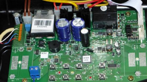
On the right, the header below the ribbon cable is marked PROGRAMMER. There is 5 pin socket to the left of that marked ICSF. I probably can't do much more than look at it because to do else may void the 4.5 years of remaining warranty. I have a lot of great advice and I'm going to sit back and see what approach to take. That is something like what WW suggested or what Mick has suggested. I like the ideas of Gordz but I am probably not going to be able to do much in that direction. |
||||
| bigmik Guru Joined: 20/06/2011 Location: AustraliaPosts: 2981 |
Bob, If you want to get at the header cable without causing any damage make yourself a male-female. `breakout cable' that way you can then attach test wires to and see if you can sense any position pulses. That way you dont need to patch into the ribbon itself (thus voiding warranty). Mick Mick's uMite Stuff can be found >>> HERE (Kindly hosted by Dontronics) <<< |
||||
| BobD Guru Joined: 07/12/2011 Location: AustraliaPosts: 935 |
OK, I've thought about what to do and getting into the door controller is probably not the way. It's in a too difficult position with very limited physical access. The door controller has two door status LEDs on it and they do a great job of reporting where the door is and what's happening. See the diagram. I thought I could mount a couple of optical sensors over the top of these indicators and report the info to a Micromite. Then use the Micromite to report by wireless to another nearby Micromite which would duplicate the status indicators. Here is where I need help. Recommendations for optical sensors and a wireless device. 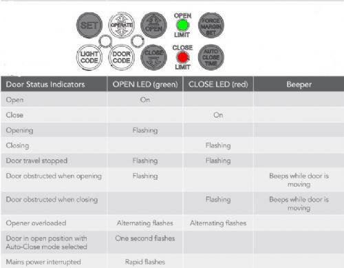
|
||||
| WhiteWizzard Guru Joined: 05/04/2013 Location: United KingdomPosts: 2991 |
Hey Bob, good to see you're still working on this! To detect the LEDs you could use a single RGB light sensor such as this one. It outputs I2C so easy to interface to a MicroMite. Regarding RF, I would personally use the Hope RFM12b module. Nice and cheap, good indoor range, low power, and again are easy to control with a MicroMite (once they have been configured properly that is!!). These are just to give you some feedback - I'm sure others will give their ideas too. WW |
||||
| BobD Guru Joined: 07/12/2011 Location: AustraliaPosts: 935 |
Phil Thanks for the advice. The optical board looks too big to fit the available space and I would need two of them. The ideal would be a device the size of a 5mm LED. I could mount two of them quite easily. The RF solution looks good. Bob |
||||
| Page 1 of 2 |
|||||
| The Back Shed's forum code is written, and hosted, in Australia. | © JAQ Software 2026 |
