
|
|
Forum Index : Microcontroller and PC projects : MM2: 2.4" SPI Colour Touchscreen
| Page 1 of 3 |
|||||
| Author | Message | ||||
| matherp Guru Joined: 11/12/2012 Location: United KingdomPosts: 11604 |
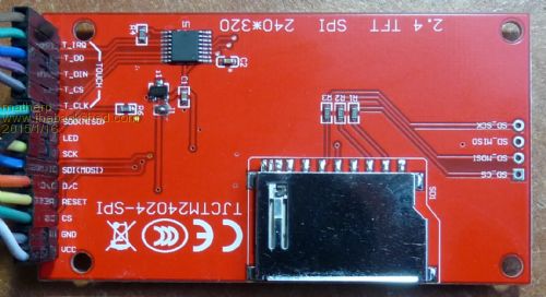
The SPI version of the ILI9341 touchscreen arrived yesterday so I've modified the various routines to make it work and fully implemented the routines to drive the XPT2046 touch controller chip. This all works much better than the analogue touch outputs on the Arduino shields. Both the ILI9341 and XPT2046 are SPI devices so they are both connected to SPIout (pin 3), SPIin (pin 14), and SPIclk (pin 25). Additional pins are used for chip select etc. as follows: I9341_CS=6 'chip select for the ILI9341 I9341_CD=4 'command/data select for the ILI9341 I9341_RESET=5 'hardware reset line for the ILI9341 T_IRQ=2 'Touch registered output from the XPT2046 T_CS=7 'chip select for the XPT2046 The I9341_CS and I9341_CD pins are fixed as they are used in the cFunctions, the others can be changed in the basic program as required. Note that the SPI data rate for the display is running at maximum speed (12Mbs). However, the XPT2046 controller can't accept this rate so the SPI clock register is modified in the T.Getdata routine to slow the data for the touch controller and then restored at the end of the routine. AS always, the code can be used on a 44-pin Micromite by mapping the underlying port/pin combinations using the PIC32MX170 datasheet and changing the basic code assignments to match. The cFunctions will work as-is. I've also spent time optimising the size of the cFunctions and reduced the font table to just the normal printing characters - this has made a huge change to program size. There are three programs in the zip file: 2015-01-16_152147_ILI9341SPI.zip ILI9341ser.bas does a complete demo and test of the graphics and text drawing routines. ILI9341calibratetouch.bas uses the graphics routines and the touch routines and displays the coordinates wherever the screen is touched. This allows you to note down the maximum and minimum coordinates of the display screen for use in calibrating touch applications. In my case the x coordinates run backwards. ILI9341touchdemo.bas is a demo painting program using the touch input and graphics routines. Touching just below the drawing area on the left side clears the screen. Touching one of the colour blocks at the top of the screen changes drawing colour. The coordinates from the calibrate routine are used to define the xmin, xmax, ymin and ymax parameters. The software scales the touch position to the screen coordinates to draw the trace including reversing the sense of the raw x-coordinate. I've also attached a zip file of the c-code: 2015-01-16_155455_ILI9341.zip The third picture shows the bottom of the PCB. There is a shorting link just below the small three pin voltage regulator. For 3.3V usage with our Micromites this link should be made to bypass the regulator. For applications where the size is right, this display is much the most effective of all of the ones I've tried. It updates fast despite being SPI and the touch system is properly implemented using a dedicated controller. Also as both controllers are SPI, pin usage is minimised and there is no use of other special function pins such as COM1 and I2C. The display I used is this one 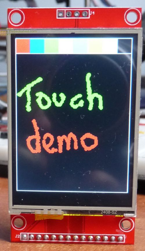 
|
||||
| matherp Guru Joined: 11/12/2012 Location: United KingdomPosts: 11604 |
YouTube video of the demo code posted. |
||||
| WhiteWizzard Guru Joined: 05/04/2013 Location: United KingdomPosts: 2991 |
Another brilliant piece of work . . . 
PS: Do you ever sleep?? 
Just ordered three to play with - due to arrive on Valentines day! |
||||
| twofingers Guru Joined: 02/06/2014 Location: GermanyPosts: 1767 |
Hi Peter Very impressive and greatly appreciated. Thanks a lot! Germans should try to buy this LCD on ebay.com (~5�). Regards Michael causality ≠ correlation ≠ coincidence |
||||
bigmik Guru Joined: 20/06/2011 Location: AustraliaPosts: 2981 |
Peter, I think you have done it... That looks (to me anyway) to be the perfect companion for the micromite.. Colour, Touch and fast display and above all CHEAP. I doubt I will use LCDs any more after this fantastic piece of work. Congratulations
Regards, Mick Mick's uMite Stuff can be found >>> HERE (Kindly hosted by Dontronics) <<< |
||||
Grogster Admin Group Joined: 31/12/2012 Location: New ZealandPosts: 9985 |
Excellent work.  Smoke makes things work. When the smoke gets out, it stops! |
||||
| matherp Guru Joined: 11/12/2012 Location: United KingdomPosts: 11604 |
Thanks for the kind words. I realised by cutting down the font array, this has lost some characters which may be useful such as � and the degree symbol. To counteract this I've added a couple of lines of code to the pstring cFunction and added an extra basic wrapper "pbitmap" This allows you to use any integer between 0 and &HFFFFFFFFFFFF to define any arbitrary 8x6 (height x width) printable character as a bitmap in a single integer. All the normal facilites of pstring are available: size, orientation, coordinates of top-left pixels (from the point of view of the character) The layout of the bitmap needed is as shown below where 2-0 means bit-0 of the second hex character from the left end. Note that for a normal text character positions 11 and 12 will be zero to give the space between characters. 2-0 4-0 6-0 8-0 10-0 12-0 2-1 4-1 6-1 8-1 10-1 12-1 2-2 4-2 6-2 8-2 10-2 12-2 2-3 4-3 6-3 8-3 10-3 12-3 1-0 3-0 5-0 7-0 9-0 11-0 1-1 3-1 5-1 7-1 9-1 11-1 1-2 3-2 5-2 7-2 9-2 11-2 1-3 3-3 5-3 7-3 9-3 11-3 So HEX FE81818181FF is a 6x8 box with the top leftmost corner missing. The attached code demonstrates this new facility. Please cut and paste the entire program above "sub I9341_test" into the previous versions to get access to this new facility. 2015-01-17_155304_font.zip |
||||
halldave Senior Member Joined: 04/05/2014 Location: AustraliaPosts: 121 |
Peter, Fantastic work... I've just ordered 3 TFT's ... now the wait regards David |
||||
TassyJim Guru Joined: 07/08/2011 Location: AustraliaPosts: 6543 |
All you need now is "font-o-Mite" A simple utility for creating those missing characters. Nothing to install, just download and unzip. Click on the pixels to toggle them on or off. The HEX characters are in the lower box ready to copy and paste. You can also paste HEX characters (with or without the leading "&H") 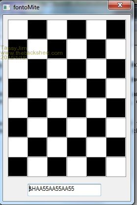
2015-01-18_052153_fontoMite.zip Something to play with while I wait for the display modules to arrive. Jim VK7JH MMedit |
||||
| G8JCF Guru Joined: 15/05/2014 Location: United KingdomPosts: 676 |
Brilliantly Simple ! The only Konstant is Change |
||||
| TassyJim Guru Joined: 07/08/2011 Location: AustraliaPosts: 6543 |
Glad you like it. My next task is to take the font data as presented in Peter's cfunctions and swap the order so they display correctly without having to do a manual swap. That will make modifying characters easier. I was also considering making it a 4 x 2 display of characters so you can create characters that flow across character boundaries. Jim VK7JH MMedit |
||||
| TassyJim Guru Joined: 07/08/2011 Location: AustraliaPosts: 6543 |
The new improved version. 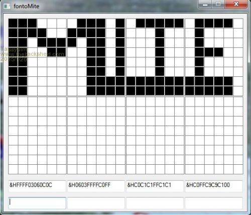
You can create 8 characters at once. Useful for high-res characters. Single click on a pixel to toggle the colour. Double click to invert all pixels for that character. Clear the text area to clear the character. You can cut and paste a number from Peter's font cfunction and font-o-mite will recognise the format. This makes starting with a preformed character easier. Right click to swap the HEX value from normal hex numbers to the layout used in cfunctions. Useful if you want to paste the altered character back into the font cfunction array. 2015-01-20_065811_fontoMite.zip Jim VK7JH MMedit |
||||
| tjwd Newbie Joined: 14/02/2015 Location: AustraliaPosts: 6 |
Hi, I am looking for information on interfacing a 2.4" SPI ILI9341 / XPT2046 to a 44 pin Micromite mk2 and found Matherp's great efforts in writing the graphics libraries. Reading Matherp's notes, I noticed the following : "....Both the ILI9341 and XPT2046 are SPI devices so they are both connected to SPIout (pin 3), SPIin (pin 14), and SPIclk (pin 25). Additional pins are used for chip select etc. as follows: I9341_CS=6 'chip select for the ILI9341 I9341_CD=4 'command/data select for the ILI9341 I9341_RESET=5 'hardware reset line for the ILI9341 T_IRQ=2 'Touch registered output from the XPT2046 T_CS=7 'chip select for the XPT2046 The I9341_CS and I9341_CD pins are fixed as they are used in the cFunctions, the others can be changed in the basic program as required. ....AS always, the code can be used on a 44-pin Micromite by mapping the underlying port/pin combinations using the PIC32MX170 datasheet and changing the basic code assignments to match. The cFunctions will work as-is." I looked in v1.0 and v1.2 of Matherp's ILI9341 libraries and they both use CD=pin 4 and CS=pin 6. As I don't have the display for testing I would like to know whether I have misunderstood the notes and can just reassign CS without recompiling the cFunctions ? Or has this been changed in v1.2 ? Any help or tips will be greatly appreciated. Regards, tjw. |
||||
| twofingers Guru Joined: 02/06/2014 Location: GermanyPosts: 1767 |
This should work (touch not testet yet): MM-PIN�����������Display
VCC��������������VCC (3.3V) GND��������������GND 2����T_IRQ�������T_IRQ (touch) 3����SPIout������SDI(MOSI) 3����SPIout-T����T-DIN (touch) 4����I9341_CD����D/C 5����I9341_RESET�RESET 6����I9341_CS����CS 7����T_CS��������T_CS (touch) 14���SPIin�������SDO(MISO) 14���SPIin-T�����T-DO (touch) 25���SPIclk������SCK 25���SPIclk-T����T-CLK (touch) causality ≠ correlation ≠ coincidence |
||||
| tjwd Newbie Joined: 14/02/2015 Location: AustraliaPosts: 6 |
Hi Twofingers, thanks for looking and taking the time to posting the connection details; it looks like the correct connections to be used with the 28 pin micromite. Geoff's documentation for the 44 pin micromite shows pin 6=ground and pin 7=bypassed with 47u cap so the CS signals must be moved when using the 44 pin micromite. Matherp's original post also states the I9341_CS=pin 6 and should not be changed due to the cFunctions. Unfortunately I do not have the display at the moment to test with a 44 pin micromite. Regards, tjw. |
||||
| twofingers Guru Joined: 02/06/2014 Location: GermanyPosts: 1767 |
@tjwd I can say nothing about 44-pinners. I only own 28-pinners. Maybe Peter can ... Regards Michael causality ≠ correlation ≠ coincidence |
||||
| matherp Guru Joined: 11/12/2012 Location: United KingdomPosts: 11604 |
Pin 4 on the 28-pin is portB.0 portB.0 on the 44 pin is 21 Pin 6 on the 28-pin is portB.2 portB.2 on the 44 pin is 23 With all Cfunctions that use "fixed" pins on one chip they can be moved by doing this mapping using the PIC32MX170 datasheet |
||||
| tjwd Newbie Joined: 14/02/2015 Location: AustraliaPosts: 6 |
Hi, thanks for your reply, it makes sense to me now ! I should have thought about it more since your original post did specify mapping the ports by referencing the datasheet - I will now be able to connect it and enjoy. Regards, tjw. |
||||
| matherp Guru Joined: 11/12/2012 Location: United KingdomPosts: 11604 |
Remember you do need to change the pin numbers in the Basic setpin commands. These are used to set up the data-direction (TRIS) registers in the PIC. This then allows the Cfunctions to work as-is |
||||
| WhiteWizzard Guru Joined: 05/04/2013 Location: United KingdomPosts: 2991 |
Hi tjwd, Sorry I've been off-line for a few days and hence unable to chime in earlier. I can confirm the module works well on the 44-pinner with the pin numbers outlined by matherp. I have several up and running without any issue. One word of warning - make sure you have a TFT module with the touch chip installed (some have it missing and hence no touch feature!!) If you have any difficulty then please let us know . . . . WW |
||||
| Page 1 of 3 |
|||||
| The Back Shed's forum code is written, and hosted, in Australia. | © JAQ Software 2026 |
