
|
|
Forum Index : Microcontroller and PC projects : Porting a little Arduino code....
| Author | Message | ||||
Grogster Admin Group Joined: 31/12/2012 Location: New ZealandPosts: 9975 |
Hi folks. 
I have some of these LED displays from eBay on order, and I have been able to find the technical docs for this thing. You can find the schematic etc at this link. It is reasonably simple logic driving circuits by the look of it, and I see they give some example Arduino code, but I have no idea how to read that code, as I have never ever touched an Arduino, so I know nothing at all about Arduino code. 
It looks to me like they define a character table in the line starting with LED_SEG_TAB at the top of the code, so I am guessing I can steal these hex values, as someone has already worked that bit out for me. I would probably shove that data into an array, so that I could just call the element from the array for the number I want to show - that bit seems easy enough. However, how to do the shift-out kind of commands with the MicroMite, would be where I would get stuck, so if anyone can help me out, that would be great. Don't port the code for me - I won't learn anything that way, but some pointers would be very helpful. Smoke makes things work. When the smoke gets out, it stops! |
||||
centrex Guru Joined: 13/11/2011 Location: AustraliaPosts: 320 |
Hi Grogster No joy finding a schematic on the link. Cliff Cliff |
||||
TassyJim Guru Joined: 07/08/2011 Location: AustraliaPosts: 6538 |
There have been a few people here who have used the 74HC595 chip so do a search of the forum and I am sure the gory details will appear. I have some here but like most things, it is still in the to-do pile. Jim VK7JH MMedit |
||||
| Grogster Admin Group Joined: 31/12/2012 Location: New ZealandPosts: 9975 |
Hi folks. @ centrex - Here is another attempt at the link to the info. @ TassyJim - I will have a search around the forums. I have a feeling I can do something with the pulse command and a loop. The tinkering continues.... EDIT: No, TBS software does not like the parenthesis in the link. You will have to copy the text link below, and paste-and-go in your browser. http://www.electrodragon.com/w/4-Digi,_7-segment_LED_Display _Module_(595_Static_Control,_Arduino_Supported) EDIT: I found this thread, which is just about exactly what I want to do. My thoughts are now steering towards using SPI. Smoke makes things work. When the smoke gets out, it stops! |
||||
| matherp Guru Joined: 11/12/2012 Location: United KingdomPosts: 11499 |
The 74HC595 documentation is stupidly confusing but the chip is very easy to use. We can assume that there are 4 chips to drive the 4 displays. These will be daisy-chained together. This is the header from my use of the 74HC595 to drive a parallel display: dim integer LT_latch=7 'b3 connect to pin 12 on all 74HC595 DIM integer Master_reset=15 ' connect to reset on all 74HC595 (pin 10) ' SPI Clock - connect to pin 11 on both 74HC595 ' SPI Out - connect to pin 14 on first 74HC595 ' connect pin 14 on second 74HC595 to pin 9 on first, etc. ' connect pin 13 (output enable) on both 74HC595 to GND pin(LT_latch)=0 setpin LT_latch,dout If it is 4 chips use SPI OPEN 1000000,3,32 to send all the data in one go then: i=spi(&HFFFFFFFF) pulse LT_latch,0.01 should light all the display elements |
||||
| Grogster Admin Group Joined: 31/12/2012 Location: New ZealandPosts: 9975 |
Hello.
Here is the circuit for the display, stolen from an image on the link above: 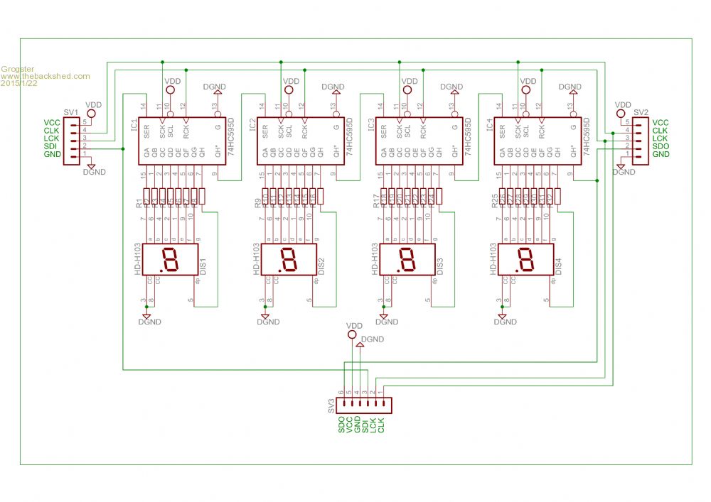
From what I can see, all 595's are daisy-chained together(you are right!), so to show any four digits, I need to clock 32 bits to the display, then clock the RCK line, which should pass that data through to the segments, lighting up what is needed. While clocking the 32-bit data to the display, I get the impression that the display will not change, until you clock the RCK line. Each time you do that, whatever bits are loaded into the registers will be reflected in the output - in this case, LED segments. Smoke makes things work. When the smoke gets out, it stops! |
||||
| Grogster Admin Group Joined: 31/12/2012 Location: New ZealandPosts: 9975 |
Do you have any bright ideas as to how I would build the 32-bit word to send to the display, representing the four digits I need? Lets start with something simple like "1234" Assuming the data from the Arduio code is right, then the 8-bit data for the numbers would be: "1"=&H60, "2"=&HDA, "3"=&HF2 and "4"=&H66. How do I combine those bytes in the correct way, to generate the 32-bit word to send? Smoke makes things work. When the smoke gets out, it stops! |
||||
| matherp Guru Joined: 11/12/2012 Location: United KingdomPosts: 11499 |
data &H7E, &H30, &H6D, &H79, &H33, &H5B, &H5F, &H70, &H7F, &H7B, &H77, &H1F, &H4E, &H3D, &H4F, &H47, &H5E, &H37 data &H30, &H3C, &H2F, &H0E, &H55, &H15, &H1D, &H67, &H73, &H05, &H5B, &H0F, &H3E, &H1C, &H5C, &H49, &H3B, &H6D Depending on how the display is wired these may give 0-9,A-Z (approximations to the letter) |
||||
bigmik Guru Joined: 20/06/2011 Location: AustraliaPosts: 2981 |
Grogster, You could always have a look at the IO Panel that I have available. Whilst the board might be too large for your application you can use the relevant parts of the circuit.. It would be a pleasure to send you one for you to play around with if you like. The difference in driving this is that each bank of 8 bits can drive an individual display and will have its own I2C address. So 4 Displays will occupy four addresses and they will not have to be multiplexed or blanked whilst a load is `rippled' in. Have a think about it. Regards, Mick Mick's uMite Stuff can be found >>> HERE (Kindly hosted by Dontronics) <<< |
||||
| matherp Guru Joined: 11/12/2012 Location: United KingdomPosts: 11499 |
dim integer a=&H12 dim integer b=&H34 dim integer c=&H56 dim integer d=&H78 dim integer s=(a<<24)+(b<<16)+(c<<8)+d |
||||
| Grogster Admin Group Joined: 31/12/2012 Location: New ZealandPosts: 9975 |
@ mick - Thanks for the offer - I will email you about it. @ matherp - Thanks a bunch! 
That last line of mathematics was what I could not get my head around.... 
You, on the other hand, seem to be rather good with the numbers. 
Smoke makes things work. When the smoke gets out, it stops! |
||||
| JohnS Guru Joined: 18/11/2011 Location: United KingdomPosts: 4335 |
Should also be able to do dim integer s=&h12345678 I hope. John |
||||
| The Back Shed's forum code is written, and hosted, in Australia. | © JAQ Software 2026 |
