
|
|
Forum Index : Microcontroller and PC projects : RelayMite 1A...
| Author | Message | ||||
Grogster Admin Group Joined: 31/12/2012 Location: New ZealandPosts: 9975 |
Hi folks. This board is 50x50, and has the full-size DIL micromite chip + four DIL relays on-board. TOP COPPER: 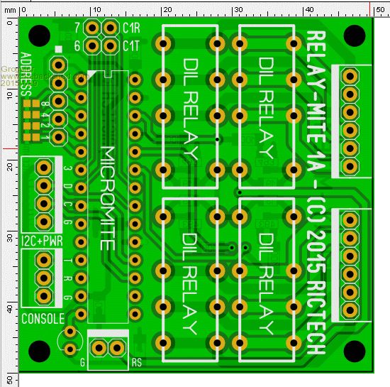
BOTTOM COPPER: 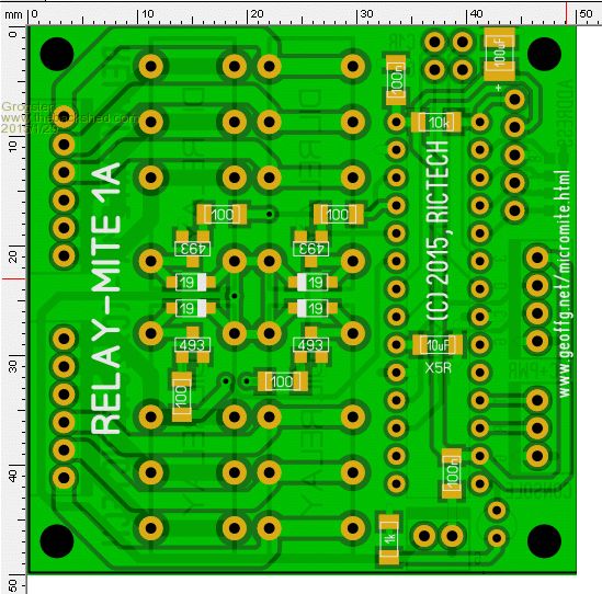
The board is designed to be connected to the I2C bus, and you can select the slave address between 0 and 15 with the four solder-blob pads. The relay supply is seperate from the MM supply, so you can use relays with different coil voltages(but they all must be the same). Full back-EMF clipping and transistor driving of the relays. COM1 is brought out to a 2x2 pin-header, along with I/O pins 6 and 7, so you can also make local use of the MM serial port, and a couple of I/O pins. If you were to daisy-chain 16 of these boards together, you would have access to 64 sets of relay contacts, all via the I2C bus, with just the two I2C lines. You could use as many as you needed, and you could also leave off relays from the board if you needed less then four. I have yet to write the MM code(that's next), but this is the board. The code will allow for momentary, latched and timed relay modes for each relay, and every relay(up to the maximum of 64) will all be addressable indivitually over the I2C bus. You can get things like this on eBay - usually about 12 relays or so, but I wanted something smaller for my next idea, and the I2C control allows you to expand the number of relays you have, just by adding more modules without having to re-design your mainboard. I will be getting a batch of boards. If anyone is interested, flick me a PM. US$07.50 for a board, including airmail to anywhere in the world. US$17.50 for a board with all the SMD fitted, including airmail to anywhere in the world. In any case, you would still need to source the through-hole parts. As soon as you get thicker then a letter here in NZ, the postage cost for airmail gets almost ridiculous... 
I will put up a link to the documents(BOM, overlay patterns, schematic etc) on this thread soon-ish. Smoke makes things work. When the smoke gets out, it stops! |
||||
| MicroBlocks Guru Joined: 12/05/2012 Location: ThailandPosts: 2209 |
No design by committee? :) (I would have suggested a GND for the com port connection) I see that pin 6 is also on the header for the serial port. That would make using RS-485 a possibility. What are the limits for voltage and current of those relays? Microblocks. Build with logic. |
||||
| Grogster Admin Group Joined: 31/12/2012 Location: New ZealandPosts: 9975 |
I'm still tweaking the PCB design, so time for a little design by committee!!!  
I will squeeze a GND in there for the COM port - good thinking. (it begins!!!!!!!!) EDIT: Oh, forgot the relay specs you asked about. Any standard DPDT relay in the DIL footprint should fit(normally referred to as HK19F's ). These can be had in several different coil voltages on eBay for about US$2 each. I am using relays with a 5v coil, but you could use 12v or 24v ones if you wanted - up to you. The contacts of my 5v ones are rated for 2A per pole @ 30v DC or 1A @ 125v AC. I have all four relays contacts wired in parallel pairs, so each DPDT relay becomes SPDT, with the rating of 4A @ 30v DC. THIS BOARD IS NOT DESIGNED OR INTENDED TO SWITCH MAINS VOLTAGE! I am guessing that most members here would realise that, but I should point that out now, to avoid any confusion. Smoke makes things work. When the smoke gets out, it stops! |
||||
| MicroBlocks Guru Joined: 12/05/2012 Location: ThailandPosts: 2209 |
:) I mentioned pin 6 for RS-485 but i should have said pin 7 as that is the COM1 EN pin. Great, that ground pin will allow an easy single cable/connector. 2A@30V is good enough for lots of projects. I would not put those contacts in parallel though. They are not guaranteed to switch simultaneously risking a higher current going through a single contact. Especially at the moment of switching a load ON there is normally a peak current (motors), and that would make that situation worse. Maybe i am overly cautious. :) There are SPDT relays available that can switch more, with a different footprint. I bought and used them before. They are around US$1.50 They are HF3FF if i remember correctly. For loads that have to be switched on for a long time, latched relays are great. They have a coil to switch on and one to switch off. This will lower power consumption a lot, and much more reliable because it does not need a holding current. A reset/watchdog will not change the output of the relay. Microblocks. Build with logic. |
||||
| WhiteWizzard Guru Joined: 05/04/2013 Location: United KingdomPosts: 2991 |
I too would consider the latching style relay. Other than that I can't add anything of value - nice board Grogs (and very useful)  |
||||
| MicroBlocks Guru Joined: 12/05/2012 Location: ThailandPosts: 2209 |
With a DPDT you can create a closed loop system. You connect the output of the relays to some input pins to read back if there is a voltage. You use the second 'pole' to provide a logic level. With SPDT you would have to probe the output or the relay and lower the voltage to a 3.3v/5v level. The biggest advantage is that you know that a latching relay is set or not set even if the uMite restarts. First read out the pins and the current state of the relays is known. This would be important if controlling equipment has to be safe. Maybe a little too much for this project,but it really depends on what you are going to use it for. This is what you get when a committee is involved. :) Microblocks. Build with logic. |
||||
| Grogster Admin Group Joined: 31/12/2012 Location: New ZealandPosts: 9975 |
I was originally going to have all six connections for each relay, out to pins, but I did not have the space. There is no reason why I could not use a double-row pin header and get ALL the connections out to pins, so that each relay would then be true DPDT, but this would mean the PCB tracks will HAVE to be much smaller to get them all in, which will affect the current handling ability. This may, in reality, prove to not be that much of a concern. Even 1mm tracks should be able to handle 500mA no problem, and 1A as a maximum I would think. It also depends on the copper weight(thichness of laminate), and you can add solder coating to the thin tracks(making them thicker) so they can handle more current - there is always a way! 
I was(and still am) in the middle as to which way to do that aspect of the relays myself, so I would love some kind of responses from other members here: Q: Do you think that all the relay contacts should be available and not set as SPDT as now? Answer just needs to be YES or NO, and I will count the responses. Whichever one wins(even if there are only a few responses), will be how I configure the PCB. YES=1 so far(TZA's vote) Smoke makes things work. When the smoke gets out, it stops! |
||||
| Grogster Admin Group Joined: 31/12/2012 Location: New ZealandPosts: 9975 |
I was PLANNING to use code to allow a standard relay to stay in the latched state until commanded to release. A "True and proper" latching relay, as mentioned, has two coils for latch and release, so once in the latched state, consumes no current at all coil-wise, whereas a "Normal" relay that has been pulled in and kept that way, will always be sucking current, but to be honest, this board was never thought of for battery operation. That said, I just measured the current on one of my 5v coil relays, and it sucks 35mA, which I don't really even think about, if the project is not to be battery powered... Smoke makes things work. When the smoke gets out, it stops! |
||||
| MicroBlocks Guru Joined: 12/05/2012 Location: ThailandPosts: 2209 |
A more important 'feature' when using a latching relay is that it will keep the state it is in without power or logic state at a uMite pin. It needs a very deliberate pulse on one of its coils to switch state. If there is a bug in the program (watchdog) or a brownout situation (voltage supervisor) the relay will not just switch off uncontrolled. BUT that is only necessary when controlling potentially unsafe equipment. The way i see it is that you have lots of spare pins to use on the uMite. Might as well take advantage of that. Microblocks. Build with logic. |
||||
| The Back Shed's forum code is written, and hosted, in Australia. | © JAQ Software 2026 |
