
|
|
Forum Index : Microcontroller and PC projects : Car temperature sensor circuit
| Author | Message | ||||
| MolsonB Regular Member Joined: 25/01/2015 Location: CanadaPosts: 48 |
My first sub routine in my quest to create an engine monitoring system. Most car temperature and air sensors are Negative temperature coefficient. NTC means the thermistor's resistance decreases as the temperature rises. MicroSquirt has a nice write up on them. http://www.useasydocs.com/theory/ntc.htm 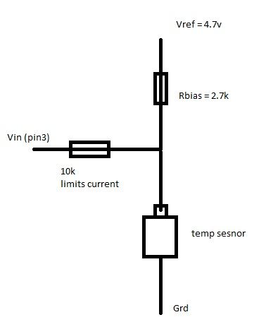
init_IO()
print "Pin 3:" Pin(3) "V" tempSensor(3) print "Temp:" TF "F" print "Temp:" TC "C" Sub init_IO() setpin 3,1 End Sub SUB tempSensor(PinNbr) 'Negative Temperature Coefficient Thermistors Local SHa, SHb, SHc, VRef, VIn, Rb, Rs SHa = 0.001664747834 SHb = 0.000210327648 SHc = 0.00000017870915 VRef = 4.7 Rb = 2673 'Actual measurement of resistor VIn = Pin(PinNbr) Rs = Rb*(1/((VRef/VIn)-1)) 'Voltage divider reversed to find temp sensor resistor TK = 1/(SHa+(SHb*LOG(Rs))+(SHc*(LOG(Rs)^3))) ' Steinhart-Hart equation TC = TK-273.15 'Celsius TF = TC*1.8 + 32 'Fahrenheit End SUB The analog inputs have a limit of 3.3v max, so every sensor input would need a voltage divider? If I measure the volts with a DMM, they are slightly (20-100mv) off what the Maximiate reads, not sure why yet. MkII 44pin - v5.0 ColorMax 2 - v4.5 |
||||
TassyJim Guru Joined: 07/08/2011 Location: AustraliaPosts: 6538 |
You can work out the maximum possible voltage at the sensor (ignoring open circuit conditions). Being a cold climate where you live, I would use minus 20 degrees C. Provided the voltage is less than 3.3V, you don't need a voltage divider. The 10k input resistor should protect the 'mite if there is an open circuit. The voltage that the 'mite reports is relative to the supply voltage so if is not exactly 3.3V, there will be an error. You can either adjust the formula to suit the supply voltage or use an external voltage reference and calibrate to that. Any electronics in a car is going to be subject to some nasty interference so there might be a lot of input protection needed and any protection is likely to interfere with the voltage readings. Jim VK7JH MMedit |
||||
disco4now Guru Joined: 18/12/2014 Location: AustraliaPosts: 1127 |
The special pin(0) function detailed in the MMBasic manual reads the internal reference voltage expected to be 1.2 volts. So (PIN(0)/1.2) should give a compensation if the supply voltage varies from 3.3 volts. You could try multiplying your read voltage by (PIN(0)/1.2) to see if you get any closer to what you expect.eg. VIn = Pin(PinNbr) * (PIN(0)/1.2) Regards Gerry F4 H7FotSF4xGT |
||||
| MolsonB Regular Member Joined: 25/01/2015 Location: CanadaPosts: 48 |
I worked out my a,b,c finding 3 references using Thermistor Calculator. http://www.thinksrs.com/downloads/programs/Therm%20Calc/NTCC alibrator/NTCcalculator.htm At 3.3 and my bias resistor, the temp will be +2C. Once I figure out the voltage, I can play with the bias resistor to move my limits. I'll dig out an LM7805 5 volt regulator and play with that. Gerry, I can't find anything about 'special pin(0)' ? Print PIN(0) comes back as 0 MkII 44pin - v5.0 ColorMax 2 - v4.5 |
||||
| TassyJim Guru Joined: 07/08/2011 Location: AustraliaPosts: 6538 |
pin(0) is an internal 1.2V reference but it is only on Micromite Mk2 with MMBasic 4.6 Jim VK7JH MMedit |
||||
| MolsonB Regular Member Joined: 25/01/2015 Location: CanadaPosts: 48 |
Oh I should update my sig. I have the ColorMax 2 ver 4.5 I hooked an up LM7805 5v reg, still chip input and dmm don't match. 20mv-40mv off. I did learn the power ground and chip ground are isolated from each other What am I missing here with analog input? I should be able to get values closer in volts. The AREF looks like a dummy pin just for those Arduino shield boards? MkII 44pin - v5.0 ColorMax 2 - v4.5 |
||||
| The Back Shed's forum code is written, and hosted, in Australia. | © JAQ Software 2026 |
