
|
|
Forum Index : Microcontroller and PC projects : 128x64 OLED SSD1306 - I2C Help
| Author | Message | ||||
| KRZ3 Newbie Joined: 31/12/2014 Location: United StatesPosts: 38 |
Hello everyone, I'm new to the Back shed and Micromite and I'm coming over from Picaxe land. With a lot of thanks to Grogster I'm slowing converting some code over. I wanted to add a OLED screen to one of my projects and I bought this one OLED. I hooked it up the I2C pins on the micromite and copied matherp's SSD1306 I2C code in MMEdit and all I get is a blank screen. Any ideas? Thanks for any help! Keith |
||||
| KRZ3 Newbie Joined: 31/12/2014 Location: United StatesPosts: 38 |
I will add I get Starting initialization Using 0.96inch I2C SSD1306 in the micromite chat and that is all |
||||
Grogster Admin Group Joined: 31/12/2012 Location: New ZealandPosts: 9073 |
Hello. 
As far as I know, matherps fantastic Cfunctions for displays are for SPI or parallel interface. I don't recall seeing a matherp Cfunction for I2C displays, but I might have missed it..... Being I2C, I would imagine that you SHOULD be able to do whatever you need to do on the screen, with simple I2C commands - you will need to check the manual for the driver IC, which should list the I2C commands it supports, and what they do. Do you have 4k7-ish pull-up resistors on the I2C lines? EDIT: Whoops - sorry. So there is some I2C code then. Smoke makes things work. When the smoke gets out, it stops! |
||||
| KRZ3 Newbie Joined: 31/12/2014 Location: United StatesPosts: 38 |
I tried the pull-up resistors and nothing. |
||||
| Grogster Admin Group Joined: 31/12/2012 Location: New ZealandPosts: 9073 |
Interesting. As I don't have that display, or that much experience with I2C displays in general, I will bow out at this point, and let others post replies. I am sure they will - people are pretty helpful here.
Welcome to the forums. Smoke makes things work. When the smoke gets out, it stops! |
||||
| Frank N. Furter Guru Joined: 28/05/2012 Location: GermanyPosts: 815 |
Hi Keith, your display should work! It has the same adress (hex 3C) as in Matherps code and should work with 3V. Did you connected SDA to SDA and CLK to CLK? Which pullups did you use? Welcome to the forums. Frank |
||||
| WhiteWizzard Guru Joined: 05/04/2013 Location: United KingdomPosts: 2794 |
Hi Keith, Can you confirm you are using the latest code (found in this link)! And welcome aboard . . . . WW PS: How are you powering the display? If you give pin connections between MicroMite and OLED that you have then that may point to a clue  For everything Micromite visit micromite.org Direct Email: whitewizzard@micromite.o |
||||
| KRZ3 Newbie Joined: 31/12/2014 Location: United StatesPosts: 38 |
Thanks everyone for looking into this. I am running the code posted here the 128x64 OLED SSD1306 - I2C. I have a 6V battery to 3.3V regulator. I have 3.2V at the screen. I also tried a separate battery pack to the screen at 4.5V. I have SDA going to Pin 18 I2C Data and SCL going to pin 17 I2C clock, 28 pin chip. I have a 4k7 resistor on both of the lines going to the 3.3V positive rail. I can try the other code White Wizzard pointed out. Maybe it is different than the update one posted. I don't know a lot about the MicroMite or I2C so maybe I'm missing something obvious. I copied the code and pasted it into MMedit. I loaded the code and typed run assuming it would then run the demo code?? In the chat com it seems like it stalls out at OLED.Init i2caddr,0 as it never prints "starting main". I have the other screen they sell too. Same thing without the linker board. I changed the resistors to match the I2C pattern on the back and I get nothing with that as well. |
||||
| WhiteWizzard Guru Joined: 05/04/2013 Location: United KingdomPosts: 2794 |
Understand that not all screens are equal (even those containing the same controller chip). There are many variants coming out from China with slight 'tweaks' required in the set-up code. matherp who has advanced all the MicroMite code for use with TFTs and OLEDs may need to chip in here. It sounds like you have everything connected ok. The only thing I can immediately think of is to actually check your leads are ok (and if mounted on a breadboard to check this is ok). Keep us posted with progress! . . . . For everything Micromite visit micromite.org Direct Email: whitewizzard@micromite.o |
||||
| KRZ3 Newbie Joined: 31/12/2014 Location: United StatesPosts: 38 |
Will do. I will check it out again when I get home. Thanks for your help! It sounds like I need to go shopping again. I wanted to stick with the I2C to save pin space, but maybe I will go to the 44 and a TFT display. |
||||
| matherp Guru Joined: 11/12/2012 Location: United KingdomPosts: 8600 |
When used for I2C the serial-in and serial-out pins to the display must be tied together, otherwise I2C, where they share a pin, won't work. The arduino world has produced a hack to allow i2C to work without receiving acks and naks from the slave. This can only be done by bitbanging the I/F. It is possible that this display isn't correctly set up for i2c in which case you need to mod it. Pins 19 an 20 from the display need to be connected together. I did this on one display which had the problem with a blob of solder. I'm trying to find the reference for the pinout but hopefully the picture will help I can't think of any other reason why the code wouldn't work if wired correctly. 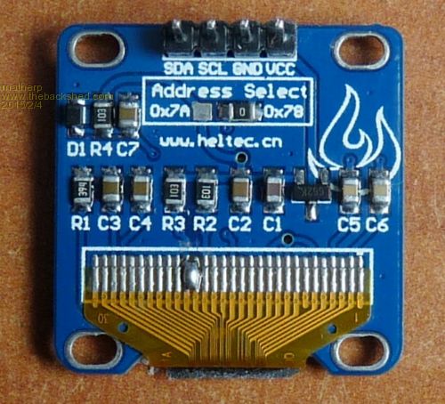
|
||||
| KRZ3 Newbie Joined: 31/12/2014 Location: United StatesPosts: 38 |
Great!! thanks for the tip and I will try that when I get home. I have the data sheet and it mentions connecting the two serial pins together. I just assumed this was done already with the linker board and by moving the resistors on the other board. More than likely this could be the fix! Thanks! |
||||
| matherp Guru Joined: 11/12/2012 Location: United KingdomPosts: 8600 |
Sorry - just found the reference. You need to connect BS1 (pin 20 to VCC pin 21) to put it properly into I2C mode as in the picture. Make sure BS1 isn't tied hard to ground without a resistor. |
||||
| KRZ3 Newbie Joined: 31/12/2014 Location: United StatesPosts: 38 |
Thanks! I will check it out and make the changes. |
||||
| KRZ3 Newbie Joined: 31/12/2014 Location: United StatesPosts: 38 |
It works! Soldering the two pins together brought it to life. 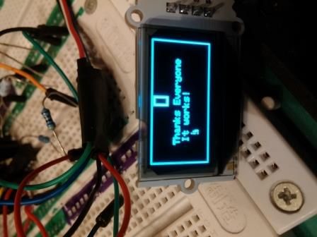
|
||||
| Grogster Admin Group Joined: 31/12/2012 Location: New ZealandPosts: 9073 |
Well done. Have fun. Smoke makes things work. When the smoke gets out, it stops! |
||||
