
|
|
Forum Index : Microcontroller and PC projects : 3.3v and 5v psu
| Author | Message | ||||
| viscomjim Guru Joined: 08/01/2014 Location: United StatesPosts: 925 |
Working on a project that needs 3.3v and 5v derived from a 12v source. What is the better way to use 2 regulators... 1 - 12volts to input of 5v reg then 5v out to input of 3.3v reg. OR 2 - 12volts to input of 5v reg AND input of 3.3v reg. am using LDO for both. and why... Thanks!!!! |
||||
| MicroBlocks Guru Joined: 12/05/2012 Location: ThailandPosts: 2209 |
I prefer to use a 5v regulator first and then feed that 5v into the 3.3v regulator. The 3.3v then has a lot less to dissipate as heat. You also have more choice in regulators because lots of 3.3v regulators have a lower then 12v input maximum. You do have to add all of the needed current together and size the 5v regulator accordingly. If you need 2A 5v and 2A 3.3v at the same time then the 5v regulator should be able to deliver 4A, even better size up to 5A so that the regulator has some spare capacity and can perform under the maximum for most of its use. With 12v you can also use a protection diode without problem as there is a high enough voltage to begin with, make sure it allows the total current. An LDO is not necessary for the 5v, it might give you some more choice. Microblocks. Build with logic. |
||||
Grogster Admin Group Joined: 31/12/2012 Location: New ZealandPosts: 9975 |
I agree with TZA here, and that is exactly how I do my 5v and 3v3 PSU's. Feed in 9v or so into 5v reg, and feed 3v3 reg from 5v reg output in a daisy-chain. The reasons why are exactly as TZA says. If you were to feed the 3v3 reg from 9v or 12v, assuming that input voltage is OK with the reg, you will substantially increase the heat dissipation, as the regulator has to drop all those extra volts. Smoke makes things work. When the smoke gets out, it stops! |
||||
Lou Senior Member Joined: 01/02/2014 Location: United StatesPosts: 229 |
Jim, If the project is low power, eg: MicroMite + LCD display and maybe a couple LED's (total current <200ma), I prefer two MCP1703 SOT89-3 LDO regulators (one 3.3v and one 5v) both connected to the 12v supply through a series protection diode. The reason, you can solder the regulators directly to fairly small pads on a pc board and need no heat sink. The MCP1703's are rated at 16v 250ma, you can safely rate your project input voltage 6 to 14v. You could also use MCP1703's in the TO-92 package for thru hole project. If you're using a higher voltage 5v regulator with a heat sink I would use TZA and Grogs method running the 3.3v regulator daisy-chained through the 5v regulator. Lou Microcontrollers - the other white meat |
||||
| viscomjim Guru Joined: 08/01/2014 Location: United StatesPosts: 925 |
Thanks for that. Daisy chain it is... great explanations! |
||||
| robert.rozee Guru Joined: 31/12/2012 Location: New ZealandPosts: 2528 |
if the project has a similar power budget to the colour maximite, then i'd be inclined to suggest using an LM2596 buck-regulator to get you down to 5v. these can be purchased as a finished assembly complete with capacitors and magnetics for less than us$1 each on ebay (including delivery). see here: http://www.ebay.com/itm/400595983355 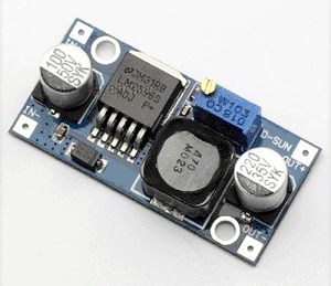
the next step, to go from the 5v down to 3v3, i'd follow what others have said and use something like the TC1262-3.3 that geoff uses on the maximite. the output of this specific device is tightly trimmed, ensuring (when a micromite or maximite is powered) that the accuracy of analog signal measurements are maintained. the rationale for the mixture of technologies is as follows: the LM2596 is good for up to around 30v at the input terminal, and can deliver a couple of amps output. because it is a switching regulator, it will step this down to 5v with around 80% or so efficiency irrespective of the input voltage. hence, little heat dissipation. the TC1262-3.3 is a good choice for going from 5v down to 3v3 because of precision regulation, low noise operation, and simplicity of design. while it will only be around 65% efficient, this matters much less for the smaller step. also, it is likely your current draw from 3v3 will be far less than that from the 5v rail. wherever possible, try to run things like relays and LEDs off the 5v line to help keep the 3v3 regulator lightly loaded and running cool. cheers, rob :-) |
||||
| MicroBlocks Guru Joined: 12/05/2012 Location: ThailandPosts: 2209 |
Rob, How do you get those efficiency numbers? It is one of those important numbers that is often hidden. Microblocks. Build with logic. |
||||
| robert.rozee Guru Joined: 31/12/2012 Location: New ZealandPosts: 2528 |
for the LM2596 i pulled the number out of thin air - it was an educated guess based upon past experience with similar PSU topologies. as it happens the guess was pretty much spot on. see the graph near the bottom of the following page: http://www.ti.com/product/lm2596 
from 12v to over 30v the graph shows a typical efficiency (with 5v output) of a tad over 80%, while the efficiency still remains above 75% as Vin drops down to a 7v low. btw, in practice i'd be reluctant to rely upon a (Vin - Vout) difference of much less than 2v. the efficiency will be affected to some degree by the choice and quality of components, but shouldn't deviate markedly from the above figures. the efficiency of the 5v to 3v3 regulator is simply (Vout / Vin), or 3.3/5 => 0.66 (about 65%). there will also be a tiny loss due to the control/ground pin current, but in most regulators these days this is extremely low. just checked the TC1262 datasheet - 80uA. cheers, rob :-) |
||||
TassyJim Guru Joined: 07/08/2011 Location: AustraliaPosts: 6538 |
I tested some of those ebay switchmodes and under no load, they draw about 11 mA from 12V. I also prefer the switchmode to 5V followed by a linear 3.3V regulator. Jim VK7JH MMedit |
||||
| The Back Shed's forum code is written, and hosted, in Australia. | © JAQ Software 2026 |
