Notice. New forum software under development. It's going to miss a few functions and look a bit ugly for a while, but I'm working on it full time now as the old forum was too unstable. Couple days, all good. If you notice any issues, please contact me.
viscomjim Guru Joined: 08/01/2014 Location: United StatesPosts: 925
Posted: 11:56am 23 Feb 2015
Copy link to clipboard
Print this post
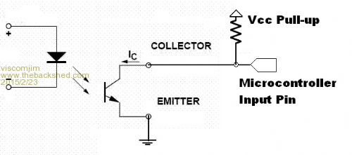
Is it okay to hookup an optocoupler to uMite and use ONLY the internal pull up resistor as shown here???
(resistor shown would be the internal pull up resistor)
P.S. switching would be low speed stuff, less than 2Hz.
Edited by viscomjim 2015-02-24
redrok Senior Member Joined: 15/09/2014 Location: United StatesPosts: 209
Posted: 12:26pm 23 Feb 2015
Copy link to clipboard
Print this post
Hi viscomjim;
Generally this is acceptable. At least for slow speed signals.
But it also "depends".
Some optocouplers have more leakage current than others especially at higher temperatures. If this leakage current is to high the input may look like a low to the input pin. So a smaller pullup would be needed.
Why do you not want to use a lower pullup resister than the internal one?
redrok
viscomjim Guru Joined: 08/01/2014 Location: United StatesPosts: 925
Posted: 12:45pm 23 Feb 2015
Copy link to clipboard
Print this post
Hi Redrok, appreciate your input!!! I am laying out a thru hole part pc board and have 5 opto couplers. So with the current limitiing resistor on the led side and a pull up on the transistor side that adds up to a lot of pcb real estate. I need to get my mind wrapped around surface mount for sure. This particular board might be a kit so surface mount is not really an option.
Anyway, I am trying to get away with eliminating 5 resistors.
Where in US are you?
Thanks!!!
Grogster Admin Group Joined: 31/12/2012 Location: New ZealandPosts: 9975
Posted: 12:51pm 23 Feb 2015
Copy link to clipboard
Print this post
I always use an external 10k pull-up for opto's, but that is just me.
I don't see any obvious reason why your idea would not work, but just as redrok says, I would be cautious of the internal pull-up, as it being 100k or so, might result in a slightly touchy sensor input, to paraphrase him for a moment....
Hook it up like that on a breadboard first, and run some tests - would only take a couple of minutes.Smoke makes things work. When the smoke gets out, it stops!
redrok Senior Member Joined: 15/09/2014 Location: United StatesPosts: 209
Posted: 01:27pm 23 Feb 2015
Copy link to clipboard
Print this post
Hi viscomjim;
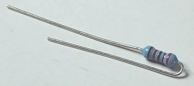
You can greatly reduce board area by using 1/10th or 1/8th watt resisters. Then install them "vertically" by bending one lead 180 degrees. Some call this the "Hair Pin" or "Bobby Pin" technique.
Ok, that image is of a 1/4th watt resistor but 1/10th is much smaller.
I'm from White Bear Lake, Minnesota.
45.081286,-93.023837
redrokEdited by redrok 2015-02-24
viscomjim Guru Joined: 08/01/2014 Location: United StatesPosts: 925
Posted: 01:35pm 23 Feb 2015
Copy link to clipboard
Print this post
Thanks for the info Grogster and Redrok! I just stumbled upon SIP resistor array. Talk about saving space. I will pull up the opto instead of using internal. Just for peace of mind.
Stay warm Red! It was 76 here today in Clearwater Florida.