Notice. New forum software under development. It's going to miss a few functions and look a bit ugly for a while, but I'm working on it full time now as the old forum was too unstable. Couple days, all good. If you notice any issues, please contact me.
panky Guru Joined: 02/10/2012 Location: AustraliaPosts: 1127
Posted: 12:34am 06 Mar 2015
Copy link to clipboard
Print this post
Has anyone created a board for the 100 pin 470? Ideally with a 3.3 reg and usb i/f ?
I don't have the time or skills to create the board and solder the chip but would like to purchase a couple of pre made systems.
Panky.
... almost all of the Maximites, the MicromMites, the MM Extremes, the ArmMites, the PicoMite and loving it!
WhiteWizzard Guru Joined: 05/04/2013 Location: United KingdomPosts: 2991
Posted: 12:57am 06 Mar 2015
Copy link to clipboard
Print this post
Hi Doug,
I haven't got a dedicated PCB yet but do have a couple of homemade PCBs that take a 100pin BoB and my USB module to give you what you need (this is how I am playing with the 100pinner MX470 and works really well.) All 100 pins available on headers too. PM me if you want me to set you a couple up!
WWEdited by WhiteWizzard 2015-03-07
Grogster Admin Group Joined: 31/12/2012 Location: New ZealandPosts: 9975
Posted: 02:14am 06 Mar 2015
Copy link to clipboard
Print this post
Not planning to do a 100-pin board at this stage.
I am waiting to see what happens with the ST port of MMBASIC to the ARM processor.
As this seems to be going very well at present, I am watching that project, to see what happens with it, before I look at doing a 100 for the 470.
Not saying that a 100 for the 470 will not happen though - just waiting to see which way the river flows first.Smoke makes things work. When the smoke gets out, it stops!
Lou Senior Member Joined: 01/02/2014 Location: United StatesPosts: 229
Posted: 03:26pm 06 Mar 2015
Copy link to clipboard
Print this post
Grogs Wrote:
Not planning to do a 100-pin board at this stage.
My druthers would be a 100 pin 470. The SkinnyMite is a most excellent board, the 100 pinner would be a great addition.
Lou
Microcontrollers - the other white meat
WhiteWizzard Guru Joined: 05/04/2013 Location: United KingdomPosts: 2991
Posted: 10:44pm 08 Mar 2015
Copy link to clipboard
Print this post
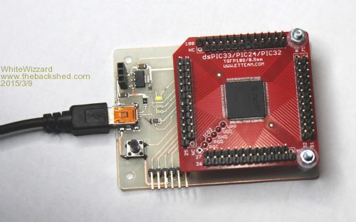
Please see below a photo showing the carrier board I was talking about (slightly customised to make a bit better than the ones I use daily). Note that this is a homemade PCB on 0.8mm board; I can get more made (possibly at a fab house) if anyone shows an interest!
The carrier board is effectively a simple interface between a popular TQFP-100 Break-Out-PCB and a computer's USB port. The BreakOutBoard plugs into the Carrier Board and is held in place with a couple of screws to give the thin 0.8mm carrier a bit more 'rigidity'.
All of the MX470's MMBasic Pins are available as male header pins and can be connected to simply by using female ended leads (and off to a BreadBoard for example). This allows you to very easily 'play' with the 100pin MX470.
Under the BoB is the onboard FTDI (GENUINE!!) chip and a couple of support components.
To the left (starting at top) is a 3-way female header providing 5v (from USB), 3v3 (from onboard LM1117 800mA reg), and 0V (nearest USB socket). The 5v supply is polyfuse protected (500mA).
Below the standard miniB USB socket is a reset switch (I find these so invaluable when testing).
To the right of the USB socket are three LEDs. The top one (green - honest) is a 3v3 power indicator. This indicates that the MX470 is getting 3v3 and effectively comes on whenever a 'powered' USB lead is connected.
Next is a Red (usb) Tx LED that flashes whenever the MX470 receives some data i.e. a keypress on TeraTerm.
The third LED is a Green Rx (usb) LED that flashes whenever the MX470 sends data to TeraTerm.
Below the LEDs is a 6-way ICSP connector. Pin 1 is on the left - when a PicKit3 is plugged in then the PicKit3's front panel will be face upwards for ease of use.
Total current consumption of the two boards is around 42mA (with all I/O pins not driving any loads).
The beauty of this set-up is that it is great for testing, and then if you actually design a circuit, the BoB can be unplugged from the carrier and run independently.
This is a slight modification to what I have been using since MatherP introduced the MX470. It has proved extremely useful and has only been modified to hopefully meet Panky's needs.
Thanks to Panky for ordering one of these! Your unit is loaded with MMBasic100 v4.6b+B10 (the latest I have from Peter).
Feedback, criticism & suggestions are welcomed . . . .
WW
Edited by WhiteWizzard 2015-03-10
panky Guru Joined: 02/10/2012 Location: AustraliaPosts: 1127
Posted: 10:45pm 09 Mar 2015
Copy link to clipboard
Print this post
Thanks a lot Phil, looking forward to assisting Peter with testing.
Great job,
Doug.... almost all of the Maximites, the MicromMites, the MM Extremes, the ArmMites, the PicoMite and loving it!
panky Guru Joined: 02/10/2012 Location: AustraliaPosts: 1127
Posted: 04:03pm 28 Mar 2015
Copy link to clipboard
Print this post
@WW
PYI Phil,
The pinout of the 3 way female is 0V, 3.3V and 5V (with the 5V closest to the USB connector) - the reverse of your statement above, No damage but it caught me out for a bit.
Cheers,
Doug.
... almost all of the Maximites, the MicromMites, the MM Extremes, the ArmMites, the PicoMite and loving it!
WhiteWizzard Guru Joined: 05/04/2013 Location: United KingdomPosts: 2991
Posted: 10:33pm 28 Mar 2015
Copy link to clipboard
Print this post
@panky
I obviously suffered a 'blonde' moment there - sorry . I can even see the USB connections so clearly in the posted photo so not sure how I slipped up. Anyway, its good to throw in the odd challenge now and again


 . I can even see the USB connections so clearly in the posted photo so not sure how I slipped up. Anyway, its good to throw in the odd challenge now and again