
|
|
Forum Index : Microcontroller and PC projects : 595 LED display hates me... :(
| Author | Message | ||||
Grogster Admin Group Joined: 31/12/2012 Location: New ZealandPosts: 9985 |
Hi folks. 
Trying to get a 595 LED display working on the SPI port on a 470. Can't get it to show up ANYTHING other then all segments on: 8.8.8.8. SetPin 1,DOUT SPI OPEN 10000,2,8 D1=SPI(&B00000000) 'Digit 1 D2=SPI(&B00000000) 'Digit 2 D3=SPI(&B00000000) 'Digit 3 D4=SPI(&B00000000) 'Digit 4 Pulse 1,1 'Latch line SPI CLOSE Do:Loop End I've tried changing the format from 3 to 2, and no-go. I have tried using hex format for the data in the SPI command, and no-go. Can anyone help me understand what I am doing wrong? Schematic of LED display(PDF) SDI is connected to SPI OUT on the 470 SDO is unconnected CLK is connected to SPI CLOCK LCK is connected to pin1 on the 470(latch line) EDIT: Was using the wrong pin for SPI out, is now on pin8 of the 470. Clock is still pin50. Latch is still pin1. I am now getting stuff on the display, but it is not what is should be - just random segments, when with all zeros, it should be setting all segments OFF. Smoke makes things work. When the smoke gets out, it stops! |
||||
disco4now Guru Joined: 18/12/2014 Location: AustraliaPosts: 1130 |
Hi Grogster, Looking at Matherp's code when using the serial to parallel chips he sets latch=0 at initialisation and then sets latch=1 followed by latch=0 to clock it through there after. Does is need a Pin(1)=0 right at the start before PIN 1 is set to DOUT. Regards Gerry F4 H7FotSF4xGT |
||||
| MM_Wombat Senior Member Joined: 12/12/2011 Location: AustraliaPosts: 139 |
From what I can see from the Schematic, Pins 8 & 13 need to be connected to gnd, and pins 10 & 16 need to be connected to vdd try that and see how you go.. AussieWombat Keep plugging away, it is fun learning But can be expensive (if you keep blowing things up). Maximite, ColourMaximite, MM+ |
||||
| Grogster Admin Group Joined: 31/12/2012 Location: New ZealandPosts: 9985 |
PROGRESS!!!!! 
Perserverence seems to be yeilding results. Two mistakes I was making: 1) Forgot to connect the LED display GND to the Micromite GND, as I was using a different supply for the LED display due to it's current consumption 2) You need to leave the SPI port OPEN once you are finished. If you close the port, the display goes all "Flickery" - probably as SPI CLOSE returns the pins to a non-configured(read: high impedance) state. Code that is working is: SetPin 2,DOUT:Pin(2)=0 SPI OPEN 1000000,3,32 D=SPI(&B10000000100000001000000010000000) Pulse 2,1 'Latch line Do:Loop This code lights all the decimal-point LED's. Replacing with all zeros for the SPI command turns all the segments off. This is how it should be. Progress!
EDIT: Lots of progress....... 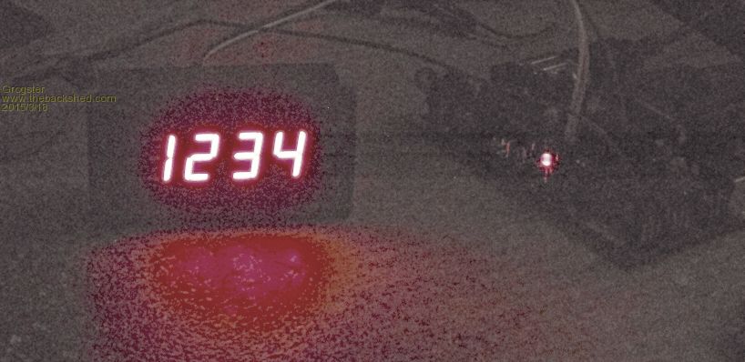
Enough for tonight. 
1:17AM here - time to rest the little grey cells.... 
EDIT: You CAN close the SPI, but you have to latch the display first, THEN close the SPI port. Makes sense, when I think about it, but it is late, so my brain is on low RPM... 
Nighty night. Smoke makes things work. When the smoke gets out, it stops! |
||||
| Grogster Admin Group Joined: 31/12/2012 Location: New ZealandPosts: 9985 |
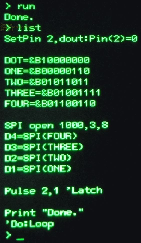
All up and running. Here is the sub that I wrote to take a standard textual input, convert that to numbers, and lookup a simple array to decode the bitmap for the segments etc. SetPin 2,dout:Pin(2)=0 'Configure display latch pin '========================================= 'SETUP SIMPLE ARRAY TO STORE DIGIT BITMAPS '========================================= Dim INTEGER DIGIT(10) DIGIT(0)=&B00111111:DIGIT(1)=&B00000110:DIGIT(2)=&B01011011 DIGIT(3)=&B01001111:DIGIT(4)=&B01100110:DIGIT(5)=&B01101101 DIGIT(6)=&B01111101:DIGIT(7)=&B00000111:DIGIT(8)=&B01111111 DIGIT(9)=&B01101111 '================= 'MAIN CODE HERE... '================= 'Demo code - can be removed. Do Input "Number to display "; N$ Input "Decimal Position "; DP LED (N$,DP) Loop End '============================================ 'SUBROUTINE TO SHOW NUMBERS ON THE LED MODULE '============================================ Sub LED (N$,DP) If Mid$(N$,1,1)="_" Then 'Detect blank request for this digit D1=0 Else D1=DIGIT(Val(Mid$(N$,1,1))) EndIf If Mid$(N$,2,1)="_" Then D2=0 Else D2=DIGIT(Val(Mid$(N$,2,1))) EndIf If Mid$(N$,3,1)="_" Then D3=0 Else D3=DIGIT(Val(Mid$(N$,3,1))) EndIf If Mid$(N$,4,1)="_" Then D4=0 Else D4=DIGIT(Val(Mid$(N$,4,1))) EndIf If DP=1 Then D1=D1+128 'Specify location of decimal point(0 for none) If DP=2 Then D2=D2+128 If DP=3 Then D3=D3+128 If DP=4 Then D4=D4+128 SPI open 100000,3,8 D=SPI(D4) D=SPI(D3) D=SPI(D2) D=SPI(D1) Pulse 2,1 'Clock the latch to make the display visable SPI CLOSE End Sub This is working very well. You can send a _ character if you want a blank digit. You specify the location of the decimal point with a number from 1 to 4. Smoke makes things work. When the smoke gets out, it stops! |
||||
Herry Senior Member Joined: 31/05/2014 Location: AustraliaPosts: 261 |
OK. Of the 4 wires from the neatly bezelled display, 1 goes to ground and 1 to 5 v, one (which one?) goes to 2 on the Micromite (I'm using 28 pin). Does the other one go to pin 3 (SPI out)? What about pin 25 (SPI clock)? Hoping my questions aren't so na’ve that I'm getting no response! Senior?! ĀWhatever it says, I'm a complete and utter beginner... |
||||
| Grogster Admin Group Joined: 31/12/2012 Location: New ZealandPosts: 9985 |
chronic PM'ed me to let me know the link to the schematic is broken. Thanks, chronic
Here is a new link. I looked for the old file, but I must have moved it. Sorry if anyone else was looking for the image - the new link should show it for you. @ Herry - I don't have any of those displays handy right at the moment, but going from the schematic, you put Vcc(supply) onto 5v supply(3v3 also works with a little less brightness), GND(ground) to ground, CLK(Clock) to SPI CLOCK, SDI(Serial Data In) to SPI OUT(MOSI), and LCK(Lock/Latch) to any spare I/O pin. As per the code above, you use the SPI port to clock the data to the module, then once that is done, you clock(pulse) the LCK line once to make the display show the data you just clocked into it. ...you may have worked all this out by now yourself...(it took me a day or so to see your post) Smoke makes things work. When the smoke gets out, it stops! |
||||
| Herry Senior Member Joined: 31/05/2014 Location: AustraliaPosts: 261 |
One thing I can't make out from the code is what is D (near the end)? It does not appear anywhere else! Also, your list of connections make up 5 but there are 6 pins. Where should SDO be connected to? I assume that the 'any spare pin' you have made pin 2 in your code. For me pin 2 is already in use and the spare will be pin 24. I assume I alter the setpin line and the Pulse line accordingly. Senior?! ĀWhatever it says, I'm a complete and utter beginner... |
||||
| Grogster Admin Group Joined: 31/12/2012 Location: New ZealandPosts: 9985 |
D is just a dummy variable to satify the SPI command. D for 'Dummy variable'.
It can be anything, but ideally not any of your other variables. EDIT: From the manual, Appendix D - SPI Commands: SDO is 'Serial Data Out', which is the line you would connect to a 2nd display module's SDI pin, if you wanted multiple displays in a daisy-chain arrangement. If you only have the one display, you simply leave SDO unconnected. On the pulse, you are correct. Adjust so that it reads Pulse 24,1 Don't forget to make pin24 an output at the top of the code.... Smoke makes things work. When the smoke gets out, it stops! |
||||
| Herry Senior Member Joined: 31/05/2014 Location: AustraliaPosts: 261 |
Got it! Just as I expected (except for SDO which I should have guessed!) Thanks a heap! Or, as we used to say in the UK -- in a richly plummy voice -- 'You are a scholar and a gentleman!' Senior?! ĀWhatever it says, I'm a complete and utter beginner... |
||||
| Grogster Admin Group Joined: 31/12/2012 Location: New ZealandPosts: 9985 |
Anytime. Smoke makes things work. When the smoke gets out, it stops! |
||||
| Herry Senior Member Joined: 31/05/2014 Location: AustraliaPosts: 261 |
Have been able to come off big work writing project and spent yesterday with the 595 and MM. Got it working. The only thing is, apart from the three digits I do want to display, I am getting odd segments illuminated before and after. I think I can nut this out but someone may be able to enlighten me and save time! Senior?! ĀWhatever it says, I'm a complete and utter beginner... |
||||
| Grogster Admin Group Joined: 31/12/2012 Location: New ZealandPosts: 9985 |
What speed are you running the SPI at? Slow it right down to minimum for a start, and see if you still have the same issue. If the issue is gone, you might just have been running the SPI too fast. The connecting cable to the display and the length of that cable starts to become more critical the faster you try to run the bus, so slow it down just for the purposes of testing.
If you are still getting odd segments where they should not be even at a slow SPI speed, then there is something wrong with the bitmaps for the digits. Double check the binary codes being sent for digits if you are using my example code, as all it takes is a zero or one in the wrong place, and you won't get what you expect on the display. Good luck, and keep us posted - I will help where I can, and others will probably chime in with other ideas if the above does not help. Smoke makes things work. When the smoke gets out, it stops! |
||||
| Herry Senior Member Joined: 31/05/2014 Location: AustraliaPosts: 261 |
Sorted. It was necessary to blank the digit I didn't need (the max I need is 3). Here's my take: 'Display module SUB DISPLAY595(NUM$)' this routine is set for 3 digits IF LEN(NUM$)=3 THEN D1 = BIDIG(VAL(LEFT$(NUM$,1))) D2 = BIDIG(VAL(MID$(NUM$,2,1))) D3 = BIDIG(VAL(MID$(NUM$,3,1))) D4=0 ELSEIF LEN(NUM$)=2 THEN D1=0 D2 = BIDIG(VAL(LEFT$(NUM$,1))) D3 = BIDIG(VAL(MID$(NUM$,2,1))) D4=0 ELSEIF LEN(NUM$)=1 THEN D1=0 D2=0 D3 = BIDIG(VAL(NUM$)) D4=0 ENDIF SPI OPEN 100000,3,8 D=SPI(D4) D=SPI(D3) D=SPI(D2)' D is a dummy variable D=SPI(D1) pulse 24,1' clock latch using 'spare' SPI CLOSE END SUB Senior?! ĀWhatever it says, I'm a complete and utter beginner... |
||||
| The Back Shed's forum code is written, and hosted, in Australia. | © JAQ Software 2026 |
