
|
|
Forum Index : Microcontroller and PC projects : LCD SCM1602C blue display for mm11 V 4.6B
| Page 1 of 2 |
|||||
| Author | Message | ||||
| banda Newbie Joined: 12/05/2014 Location: New ZealandPosts: 35 |
I've worked my way down to P20 of Micromite 11 manual. I bought an SCM1602c DISPLAY MODULE and plugged it in exactly as in the manual. I'm using v4.6b. The backlight lights up the screen, one row of dark rectangles appears on the screen, and that's all. I've written a program in MMedit which I've used successfully for all the beginner projects earlier than P20, but although it runs properly the LCD produces no text. I've checked pretty thoroughly (I believe) and I believe it uses an HD44780 controller as the manual specifies, so it should be OK. Can anyone give me a simple MMEDIT program for a 28-pin, MMII v 4.6b that will show some text on my LCD. If it works OK for you then I can analyse it and hopefully find where I am wrong. I'd show the program I've written too, but that's beyond me yet, besides it's probably wrong. Thanks for any help, Banda |
||||
| WhiteWizzard Guru Joined: 05/04/2013 Location: United KingdomPosts: 2991 |
Barry, Try adjusting the 'contrast' to the display (typically a 10k pot on Pin 3). The symptoms you describe (rectangles) imply that this may be your issue . . . . WW |
||||
| banda Newbie Joined: 12/05/2014 Location: New ZealandPosts: 35 |
I was sent a pot which I attached to pin3 of the LCD at the very beginning. It appears to work. If I knew how to show a photo of the setup I would, but how? Below is my little program. It throws up no errors, and the CHAT window shows it has run. On powerup the LCD shows blue, with one line of 16 dark rectangles. None on line 2. Nothing changes when the prog is run. It's a mystery, banda ................................................. SETPIN 23, Dout 'To RS red SETPIN 24, Dout 'To En yellow SETPIN 2, Dout 'To DB4 green SETPIN 3, Dout 'To DB5 white SETPIN 4, Dout 'To DB6 brown SETPIN 5, Dout 'To DB7 blue LCD INIT 2, 3, 4, 5, 23, 24 LCD 1, 2, "Temperature" LCD 2, 6, "TEST" ................................................. |
||||
| banda Newbie Joined: 12/05/2014 Location: New ZealandPosts: 35 |
I've adjusted the pot as high as it can go. |
||||
Grogster Admin Group Joined: 31/12/2012 Location: New ZealandPosts: 9975 |
Banda - in the "Post Reply" box that you type your post in at the bottom of the thread, you will see a row of icons just above the text window. Position your cursor where you want to insert your picture, and then click the little icon 2nd from the right on that row above - has little cyan arrow pointing up, over a graphic of a tree on some grass. When you click that, a window should pop up, and you click CHOOSE FILE button. Find your image and double-click it. You might need to drag the window out a bit to see the OK button - move your mouse to the bottom edge of the pop-up window - you will see the normal pointer turn into a double-ended arrow. Press AND HOLD the left mouse button, and move the mouse down. This should reveal an OK and CANCEL button - not sure why it is mapped like this, but this is what I have to do to see the OK and CANCEL button - you and others may not. Click OK. A line of gobble-de-gook will appear in your post as text. Ignore it(it is forum code linking to your image). Click or move your cursor to below this line of guff, and add any further comments you may want to. Hopefully, that will allow you to upload any images you want, for others to examine. EDIT: Can you please link to the module you purchased? You do THAT by clicking the little icon of the globe 4th from the left on the row of icons, and following your nose. First pop-up box will ask you for a name for the link - you can type anything you like here as a reference. Click OK. Another pop-up will appear asking for the actual link. Paste a copy of your web link in here, and click OK. Yet again, you will get another line of gobble-de-gook as text in your message, and again, this is forum code to generate the link. Smoke makes things work. When the smoke gets out, it stops! |
||||
TassyJim Guru Joined: 07/08/2011 Location: AustraliaPosts: 6538 |
You should be able to adjust the pot and the display will go from nothing (light) to dark. The setting it needs is somewhere in-between - not fully one way. One outside leg of the pot goes to gnd, the other outside leg goes to 3.3V and the centre pin goes to the contrast pin on the display. Jim VK7JH MMedit |
||||
| WhiteWizzard Guru Joined: 05/04/2013 Location: United KingdomPosts: 2991 |
As others have said, adjust the pot as it does not need to necessarily be at 'one end' of its travel. When you adjust it do the 'rectangles' that you mention fade in and out? WW |
||||
| banda Newbie Joined: 12/05/2014 Location: New ZealandPosts: 35 |
All thanks to Grogster who put me on the right track to show pics in my post. My little prog. The red LED lights at the end of the run program. 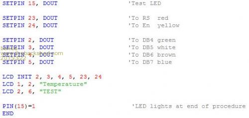
The layout, as clearly as I can. The LED is alight. 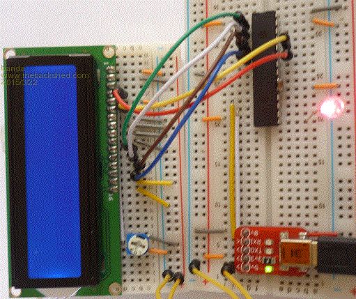
The underside of my LCD. 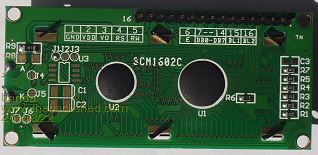
Why doesn't the stupid LCD show the text? Banda |
||||
| Grogster Admin Group Joined: 31/12/2012 Location: New ZealandPosts: 9975 |
Hiya. 
Can you please post a link to where you got your LCD? I remember you mentioning that you thought it had a compatible controller, but I would like to check and confirm that for you. I have not yet examined your images for any layout error, but others will - thanks for posting the photos - they will be of help to me and others.
The only reason I keep asking about the link for this LCD, is I did have the EXACT same problem as you seem to be having, as I was using some LCD's I had here, but they did not have compatible controllers in them. In my case, they were Topway 40x4's, and they worked fine on one PIC project, but NOT on the Micromite - just got the row of black squares you are getting. The other PIC with the code that DID work with the Topway displays, was not written by me, and was closed so I don't know what they did differently to make that one work. Fact of the matter is - you MUST have an LCD with a compatible controller if you want to have any hope of it working, so that is why I just want to double check your display for you. EDIT: I am sure you have read the manual plenty of times trying to get your LCD working, but from the manual: So, if your LCD DOES NOT use one of those three controllers, then it likely will not want to work for you - this is why we need to be 100% sure that your LCD does use a compatible controller before we get too deep in the electronic waters.  Smoke makes things work. When the smoke gets out, it stops! |
||||
palcal Guru Joined: 12/10/2011 Location: AustraliaPosts: 2039 |
Where did you get the display from is it 5v. or 3.3v. Paul. Edit. Just found the spec. and it seems to be a 5v. display. "It is better to be ignorant and ask a stupid question than to be plain Stupid and not ask at all" |
||||
| WhiteWizzard Guru Joined: 05/04/2013 Location: United KingdomPosts: 2991 |
Hi, I believe this is an LCD I supplied - known to be working type. Looking at the layout there are just two things I am looking at regarding the 10k pot: Is the 10K pot wired correctly across the supply (two ends of the 10k pot; and is the 'wiper' going to pin3? The next thing to check is continuity between each pins - check for open circuit either in a lead or a 'bad' breadboard contact strip! WW |
||||
BobD Guru Joined: 07/12/2011 Location: AustraliaPosts: 935 |
It wouldn't be the first time for crook breadboard connections to cause un-fixable bugs. |
||||
| palcal Guru Joined: 12/10/2011 Location: AustraliaPosts: 2039 |
I see now it appears you are running it from 5V. Paul. "It is better to be ignorant and ask a stupid question than to be plain Stupid and not ask at all" |
||||
| Grogster Admin Group Joined: 31/12/2012 Location: New ZealandPosts: 9975 |
If WW sold you the LCD, then it DEFINITELY will be compatible, so you can ignore all my requests for links to the module and where you bought it from. Smoke makes things work. When the smoke gets out, it stops! |
||||
| WhiteWizzard Guru Joined: 05/04/2013 Location: United KingdomPosts: 2991 |
Have you tried this yet? If so, what happened?? |
||||
| banda Newbie Joined: 12/05/2014 Location: New ZealandPosts: 35 |
To WW: When I twiddle that little thingy on the pot the 16 rectangles fade to nothing or brighten to max (which doesn't seem extremely bright to me). I have searched the web and found this. Copy the complete thing on to the web address line. It worked for me. Portuguese, but you can see the connection between scm1602c and HD44780 controller, which mmII manual says is OK. http://www.google.co.nz/url?sa=t&rct=j&q=&esrc=s&source=web&cd=20&cad=rja&uact=8&ved=0CFYQFjAJOAo&url=http%3A%2F%2Fbusca pro.com.br%2FDisplay-Tela-Lcd-16x2-Hd44780-Com-Backlight-Azul-Arduino_621280187P.html&ei=wmoPVdfjKYqF8QX7-IGoDw&usg=AFQj CNFwRrZWPXTuKPWhbV6gIUHyJVOe0w&sig2=1GlpaUFeO31kgid-SHAxOQ&bvm=bv.88528373,d.dGc banda |
||||
| banda Newbie Joined: 12/05/2014 Location: New ZealandPosts: 35 |
OK I'll try again. Copy this and paste it in the address column. http://translate.google.co.nz/translate?hl=en&sl=pt&u=http://buscapro.com.br/Display-Tela-Lcd-16x2-Hd44780-Com-Backlight -Azul-Arduino_621280187P.html&prev=search |
||||
bigmik Guru Joined: 20/06/2011 Location: AustraliaPosts: 2981 |
Hi Banda, I looked at your link wiring and it looks correct to me.. The one question I ask is the low order bits DB0-DB3 you have linked to GND.. I have always left these floating (presumably pulled HIGH) and that may be your problem.. If you rotate the pot and can see full black rectangles usually on the TOP row only and then can fade them to nothing I reckon the pot is fine... you could rotate till you see the rectangles lit and see if they change to two lines (dimmer) which means the init routine works. Try pulling the GNDs on the low order data and see how you go. If that doesn't work I would try buzzing from the uMite to the LCD module to make sure every wire is intact. Regards, Mick Mick's uMite Stuff can be found >>> HERE (Kindly hosted by Dontronics) <<< |
||||
| banda Newbie Joined: 12/05/2014 Location: New ZealandPosts: 35 |
OK I've taken those 4 GNDs out, but no result to the prog. If I was paid I could say that there is the faintest, and I mean faintest, shadow of another line of rectangles. They might even have been there before and I hadn't noticed them. If I put an LED between any of the pins 2 3 4 5 of the mmII and GND, should they light up when the prog is run? None does. banda |
||||
| BobD Guru Joined: 07/12/2011 Location: AustraliaPosts: 935 |
probably pulsing too fast to see a LED flash. A logic probe or an oscilloscope or similar will definitively show. |
||||
| Page 1 of 2 |
|||||
| The Back Shed's forum code is written, and hosted, in Australia. | © JAQ Software 2026 |
