
|
|
Forum Index : Microcontroller and PC projects : ARMmiteb18: In-built TFT display handling
| Page 1 of 2 |
|||||
| Author | Message | ||||
| matherp Guru Joined: 11/12/2012 Location: United KingdomPosts: 11498 |
Attached is the latest beta release of the Micromite code for the STM32F407. 2015-03-20_083853_ARMmiteb18.zip For details of how to get started with the ARMmite see this post. Please note the default console on this release is the UART, Console RX is on pin PA3, TX is on pin PA2. You can use OPTION CONSOLE USB to swap the console to the USB port but please note some people are finding reliability problems with this. See this post for details of how to get started with USB. This release includes full Cfunction capability and huge thanks are due to Peter Carnegie G8JCF for implementing this and helping with other "heavy" issues. Documentation on this will follow at a later date. The other main change in this release is the implementation of in-built graphics routines. The following controllers are currently supported: Parallel ILI9341P : many 2.4" and 2.8" displays with an 8-bit parallel interface ST7781 : other 2.4" displays with an 8-bit parallel interface SSD1289 : 3.2" displays with a 16-bit parallel interface SSD1963 : 5" and 7" displays with a 16-bit parallel interface SPI SSD1351 : Colour Oled displays with an SPI interface ILI9341S : many 2.4" and 2.8" displays with a SPI interface ST7735 : 1.8" displays with an SPI interface Before using a display it must be initialized. The syntax for the parallel displays is: DISPLAY OPEN displayname, command/data pin, WR pin, reset pin, databus (see below), screen width, screen height The databus parameter can be: 0:use pins PD0-PD7 (use as required for ILI9341P, ST7735) 8:use pins PD8-PD15 (use as required for ILI9341P, ST7735) 16: use pins PD0-PD15 (mandatory for SSD1289 and SSD1963) examples: DISPLAY OPEN ILI9341P,1,2,3,0,240,320 DISPLAY OPEN SSD1963,1,2,3,16,800,480 In these examples I am using pins PE2, PE3, and PE4 as the signal pins. Note that the chip-select pin on the display should be tied to GND, the RD pin on the display should be tied to VCC The syntax for the serial displays is: DISPLAY OPEN displayname, SPI port number, command/data pin, chip select pin, reset pin, screen width, screen height The SPI port number can be 1, 2, or 3 corresponding to pins labelled SPI, SPI2, and SPI3 in the pinout. Note in general SPIIN pins need not be connected but should not be used for other purposes. SPIOUT from the ARMmite connects to SPIIN on the display (may be labelled MOSI) e.g. DISPLAY OPEN ILI9341S,2,1,2,3,240,320 If you have connected a display correctly, the OPEN command will initialize it and clear the display. If it doesn't you probably have one or more connections reversed. DISPLAY CLOSE disconnects all the pins from the display and returns the pins for normal use Once the display is open there are a range of drawing commands available: DISPLAY font, xstart, ystart, foreground colour, background colour, textstring, (optional x-scale, or x and y if only this parameter specified),(Optional y-scale) 10 fonts are currently included as shown in the picture. The code includes wordwrap and protection against writing outside the screen area. All fonts can be scaled using the x-scale and y-scale parameters but note this does introduce a performance overhead. 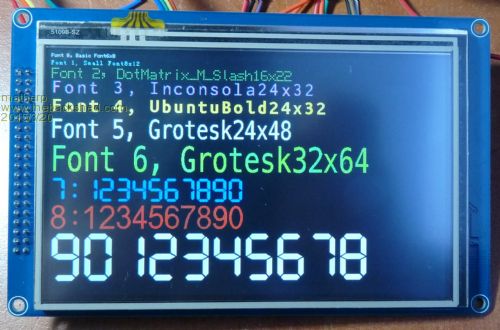
PIXEL x-coordinate, y-coordinate, colour LINE x-start-coordinate, y-start-coordinate, x-end-coordinate, y-end-coordinate, colour CLS (optional parameter colour) BOX x-coordinate, y-coordinate, width, height, colour, (optional parameter F to fill) CIRCLE x-coordinate, y-coordinate, radius, colour, (optional parameter F to fill) TRIANGLE x1-coordinate, y1-coordinate, x2-coordinate, y2-coordinate, x3-coordinate, y3-coordinate, colour, (optional parameter F to fill) BITMAP x-coordinate, y-coordinate, foreground colour, background colour, bitmap (long long integer giving 8 x 8 bitmap). The code treats this as an array of type char[8]. This is read bit7 to bit0, array-index[0] to array-index[n]. The screen then updates the 8 x 8 box top left to bottom right. RBOX x-coordinate, y-coordinate, width, height, radius of corners, colour, (optional parameter F to fill) ROTATE orientation (only supported for screens with hardware rotate support, ILI9341S, ILI9341P, ST7735, SSD1963). Orientation can be: 0: Portrait 1: Portrait 180 2: Landscape 3: Landscape 180 For displays that support it, is quite OK to repeatedly switch orientation, this allows you to write text in any orientation and then switch back to your standard orientation. In general all normal Micromite features should work as per the 4.6b manual. Other additional features include: OPTION VCC n.nnn If you measure accurately the supply voltage to the microprocessor, then using this option will calibrate both the ADCs and the DACs correctly. The option is stored in flash memory for subsequent restarts and power cycles. The Discovery board has a diode between the 3.3V regulator and the chip supply which drops the voltage, "OPTION VCC 2.92" works for my board. You can then confirm the setting by using "print pin(0)" which should then report 1.2V. Valid values are 1.8V to 3.6V - the allowable range for the chip. PWM and SERVO both support up to 8 channels with 4 on each timebase i.e. PWM 1,10000,20,40,60,80 SERVO 2,1.44,1.66,1.88,2.22 The STM32F407 has two independent onboard 12-bit DACs. The format of the Basic commands is: DAC number,voltage ' number can be 1 or 2, voltage is a float between 0 and 3.3v DAC number,STOP ' turn off the DAC There are dedicated Basic commands and functions for using pins PD0 to PD15 as a parallel databus SETPORTD databus , MODE, OPTIONS The databus parameter can be: 0:use pins PD0-PD7 (use as required for ILI9341P, ST7735) 8:use pins PD8-PD15 (use as required for ILI9341P, ST7735) 16: use pins PD0-PD15 (mandatory for SSD1289 and SSD1963) MODE can be DIN, or DOUT, or OFF to disable the port and return the pins for general use OPTIONS can be OC for output or PULLUP, PULLDOWN for input PORTD(databus)=nnn Sets the pins specified by databus to the value nnn. If databus is 0 or 8 this should be a number between 0 and 255. If databus is 16 this can be a number between 0 and 65535 variable =PORTD(databus) Reads the pins defined by databus. If databus is 0 or 8 this will return a number between 0 and 255. If databus is 16 this will return a number between 0 and 65535 The pinout is: PE2, DIGITAL_IN | DIGITAL_OUT | OC_OUT | COUNT // pin 1
PE3, DIGITAL_IN | DIGITAL_OUT | OC_OUT | COUNT // pin 2 PE4, DIGITAL_IN | DIGITAL_OUT | OC_OUT | COUNT // pin 3 PE5, DIGITAL_IN | DIGITAL_OUT | OC_OUT | IR // pin 4 PE6, DIGITAL_IN | DIGITAL_OUT | OC_OUT // pin 5 // pin 6 - VBAT PC13, DIGITAL_IN | DIGITAL_OUT | OC_OUT | SPI3CLK // pin 7 PC14, DIGITAL_IN | DIGITAL_OUT | OC_OUT | SPI3IN // pin 8 PC15, DIGITAL_IN | DIGITAL_OUT | OC_OUT | SPI3OUT // pin 9 // pin 10 - VSS // pin 11 - VDD // pin 12 - External Xtal // pin 13 - External Xtal // pin 14 - NRST PC0, ANALOG_IN | DIGITAL_IN | DIGITAL_OUT | OC_OUT // pin 15 PC1, ANALOG_IN | DIGITAL_IN | DIGITAL_OUT | OC_OUT // pin 16 PC2, ANALOG_IN | DIGITAL_IN | DIGITAL_OUT | OC_OUT // pin 17 PC3, ANALOG_IN | DIGITAL_IN | DIGITAL_OUT | OC_OUT // pin 18 // pin 19 - VDD // pin 20 - VSSA // pin 21 - VREF+ // pin 22 - VDDA PA0, ANALOG_IN | DIGITAL_IN | DIGITAL_OUT | OC_OUT // pin 23 PA1, ANALOG_IN | DIGITAL_IN | DIGITAL_OUT | OC_OUT // pin 24 PA2, Console TX // pin 25 // PA3, Console RX // pin 26 // pin 27 - VSS // pin 28 - VDD PA4, ANALOG_IN | DIGITAL_IN | DIGITAL_OUT | OC_OUT | DAC_1 // pin 29 PA5, ANALOG_IN | DIGITAL_IN | DIGITAL_OUT | OC_OUT | DAC 2 // pin 30 PA6, ANALOG_IN | DIGITAL_IN | DIGITAL_OUT | OC_OUT | PWM2A // pin 31 PA7, ANALOG_IN | DIGITAL_IN | DIGITAL_OUT | OC_OUT | PWM2B // pin 32 PC4, ANALOG_IN | DIGITAL_IN | DIGITAL_OUT | OC_OUT // pin 33 PC5, ANALOG_IN | DIGITAL_IN | DIGITAL_OUT | OC_OUT | PWM2C // pin 34 PB0, ANALOG_IN | DIGITAL_IN | DIGITAL_OUT | OC_OUT // pin 35 PB1, ANALOG_IN | DIGITAL_IN | DIGITAL_OUT | OC_OUT | PWM2D // pin 36 PB2, DIGITAL_IN | DIGITAL_OUT | OC_OUT // pin 37 PE7, DIGITAL_IN | DIGITAL_OUT | OC_OUT // pin 38 PE8, DIGITAL_IN | DIGITAL_OUT | OC_OUT // pin 39 PE9, DIGITAL_IN | DIGITAL_OUT | OC_OUT // pin 40 PE10, DIGITAL_IN | DIGITAL_OUT | OC_OUT // pin 41 PE11, DIGITAL_IN | DIGITAL_OUT | OC_OUT // pin 42 PE12, DIGITAL_IN | DIGITAL_OUT | OC_OUT // pin 43 PE13, DIGITAL_IN | DIGITAL_OUT | OC_OUT // pin 44 PE14, DIGITAL_IN | DIGITAL_OUT | OC_OUT // pin 45 PE15, DIGITAL_IN | DIGITAL_OUT | OC_OUT // pin 46 PB10, DIGITAL_IN | DIGITAL_OUT | OC_OUT | comm1 TX // pin 47 PB11, DIGITAL_IN | DIGITAL_OUT | OC_OUT | comm1 RX // pin 48 // pin 49 - VCAP1 // pin 50 - VDD // PB12, DIGITAL_IN | DIGITAL_OUT | INTERRUPT | OC_OUT // pin 51 PB13, DIGITAL_IN | DIGITAL_OUT | OC_OUT | SPI2CLK // pin 52 PB14, DIGITAL_IN | DIGITAL_OUT | OC_OUT | SPI2IN // pin 53 PB15, DIGITAL_IN | DIGITAL_OUT | OC_OUT | SPI2OUT // pin 54 PD8, DIGITAL_IN | DIGITAL_OUT | INTERRUPT | OC_OUT // pin 55 PD9, DIGITAL_IN | DIGITAL_OUT | INTERRUPT | OC_OUT // pin 56 PD10, DIGITAL_IN | DIGITAL_OUT | INTERRUPT | OC_OUT // pin 57 PD11, DIGITAL_IN | DIGITAL_OUT | INTERRUPT | OC_OUT // pin 58 PD12, DIGITAL_IN | DIGITAL_OUT | OC_OUT // pin 59 PD13, DIGITAL_IN | DIGITAL_OUT | OC_OUT // pin 60 PD14, DIGITAL_IN | DIGITAL_OUT | OC_OUT // pin 61 PD15, DIGITAL_IN | DIGITAL_OUT | OC_OUT // pin 62 PC6, DIGITAL_IN | DIGITAL_OUT | OC_OUT | comm2 TX // pin 63 PC7, DIGITAL_IN | DIGITAL_OUT | OC_OUT | comm2 RX // pin 64 PC8, DIGITAL_IN | DIGITAL_OUT | OC_OUT // pin 65 PC9, DIGITAL_IN | DIGITAL_OUT | OC_OUT | I2CSDA // pin 66 PA8, DIGITAL_IN | DIGITAL_OUT | OC_OUT | I2CSCK // pin 67 // pin 68 - USB VBUS // pin 69 - USB ID // pin 70 - USB DATA- // pin 71 - USB DATA+ PA13, DIGITAL_IN | DIGITAL_OUT | OC_OUT // pin 72 // pin 73 - VCAP2 // pin 74 - VSS // pin 75 - VDD // PA14, DIGITAL_IN | DIGITAL_OUT | OC_OUT // pin 76 PA15, DIGITAL_IN | DIGITAL_OUT | OC_OUT // pin 77 PC10, DIGITAL_IN | DIGITAL_OUT | OC_OUT // pin 78 PC11, DIGITAL_IN | DIGITAL_OUT | OC_OUT // pin 79 PC12, DIGITAL_IN | DIGITAL_OUT | OC_OUT // pin 80 PD0, DIGITAL_IN | DIGITAL_OUT | OC_OUT // pin 81 PD1, DIGITAL_IN | DIGITAL_OUT | OC_OUT // pin 82 PD2, DIGITAL_IN | INTERRUPT | DIGITAL_OUT | OC_OUT // pin 83 PD3, DIGITAL_IN | INTERRUPT | DIGITAL_OUT | OC_OUT // pin 84 PD4, DIGITAL_IN | INTERRUPT | DIGITAL_OUT | OC_OUT // pin 85 PD5, DIGITAL_IN | INTERRUPT | DIGITAL_OUT | OC_OUT // pin 86 PD6, DIGITAL_IN | INTERRUPT | DIGITAL_OUT | OC_OUT // pin 87 PD7, DIGITAL_IN | DIGITAL_OUT | OC_OUT // pin 88 PB3, DIGITAL_IN | DIGITAL_OUT | OC_OUT | SPI1CLK // pin 89 PB4, DIGITAL_IN | DIGITAL_OUT | OC_OUT | SPI1IN // pin 90 PB5, DIGITAL_IN | DIGITAL_OUT | OC_OUT | SPI1OUT // pin 91 PB6, DIGITAL_IN | DIGITAL_OUT | OC_OUT | PWM1A // pin 92 PB7, DIGITAL_IN | DIGITAL_OUT | OC_OUT | PWM1B // pin 93 // pin 94 - BOOT0 PB8, DIGITAL_IN | DIGITAL_OUT | OC_OUT | PWM1C // pin 95 PB9, DIGITAL_IN | DIGITAL_OUT | OC_OUT | PWM1D // pin 96 PE0, DIGITAL_IN | DIGITAL_OUT | OC_OUT | WAKEUP // pin 97 PE1, DIGITAL_IN | DIGITAL_OUT | OC_OUT | COUNT // pin 98 // pin 99 - VSS // pin 100 - VDD |
||||
| G8JCF Guru Joined: 15/05/2014 Location: United KingdomPosts: 676 |
Working with Peter Mather is exhausting 
The effort PeterM puts in is out of this world far in excess of anything I've contributed to the ARMMite port. The thing is that with all the memory, and I/O capabilities of these ST ARM MCUs there is so much more that can be done - as evidenced by the huge amount of devices PeterM keeps adding to ARMMite for example ! Peter The only Konstant is Change |
||||
| WhiteWizzard Guru Joined: 05/04/2013 Location: United KingdomPosts: 2991 |
Great work Peter (and Peter!) - lots of useful things to keep everyone here happy. 
So dare I ask; would it be easy to incorporate into this list the SSD1306 (which is the 'original' I2C 0.96" OLED you got working) OR would it be a right 'pain'? If doable then I believe that you have captured all the display controllers that have been mentioned here on the Shed. Am getting a SSD1963 controller board next week to test this stuff (along with the cheap ARM 'kit')
Great stuff . . . . WW |
||||
boss Senior Member Joined: 19/08/2011 Location: CanadaPosts: 268 |
@matherp Hi Peter, this release is awesome progress indeed. Maybe I found the glitch - embedded EDITOR doesn't work for me although via MMedit I everything seems be O.K. Btw. I have SSD1963 shield that allows you connect the ordinary PC monitor via DVI, but unfortunately the it use 8bit bus. It is tested and works fine. I would like to ask you if this is interesting enough to write ARMite driver or I have use the own driver with CFunction. Regards Bo |
||||
| matherp Guru Joined: 11/12/2012 Location: United KingdomPosts: 11498 |
Works for me using the hex file above. make sure you erase all before programming and put a link between boot0 and VDD while programming |
||||
| boss Senior Member Joined: 19/08/2011 Location: CanadaPosts: 268 |
@matherp Boot x VDD connected, the chip was completely erased, then flashed and verified. The result is the same. Everything looks fine, even flash x file verification (see picture). No other problem was found yet, but embedded Editor. 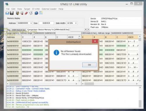
Bo |
||||
| G8JCF Guru Joined: 15/05/2014 Location: United KingdomPosts: 676 |
The inbuilt MMBasic editor should of course work, BUT, is anybody who is serious about developing an embedded application doing so directly on the target MCU ? MMEdit is a really, really, great IDE for MMBasic Peter The only Konstant is Change |
||||
| boss Senior Member Joined: 19/08/2011 Location: CanadaPosts: 268 |
Hi Peter, first I'd like say that ARMite was my dream for years (and Cfunction is above the dream). You and Peter did awesome progress with MM(Mk)basic. Thank you. Now regarding the Editor - actually I'm personally prefer MMEdit as well, but I'm always trying to test as many MMbasic features as I can. Because if somewhere is a bug it is always wise to find and correct it. Regards Bo |
||||
Grogster Admin Group Joined: 31/12/2012 Location: New ZealandPosts: 9975 |
I'll just add my 2c here - I never use the editor for more then minor changes to test things. All writing of code is in MMEDIT. Now, this is NOT to take away from the built-in editor. I think this concept was a SUPERB idea for the original series of chips, as you hook the chip up to a computer and Tera-Term or similar, and you can write and edit your program directly on the chip - that is a great feature for newcomers and beginning programming, as you don't need to worry about learing one single jot of any kind of computer-based IDE development program. On the ARMmite? Probably not much use for developing code, but still a useful tool to have there in the background, IMHO. Having said that, I would not want to develop a program for the ARMmite using only the editor, as the coloured syntax of an IDE is really, really useful for bigger sized code listings. ...again - my 2c only, as others are commenting on this at the moment.... Smoke makes things work. When the smoke gets out, it stops! |
||||
| matherp Guru Joined: 11/12/2012 Location: United KingdomPosts: 11498 |
What terminal are you using? It works with teraterm but I think the dataflow may be too fast for the MMEDIT VT100 |
||||
| boss Senior Member Joined: 19/08/2011 Location: CanadaPosts: 268 |
@matherp Terraterm 4.86 and W 8.1 pro. It behaves madly. Greeting message prints 9 times, the reset button seems not working now. I'll install one more disk and try it again with fresh installed W7. What kind od Windows you have installed? Could virus infect hex file? I don't know. b12 seems working fine. Bo |
||||
| matherp Guru Joined: 11/12/2012 Location: United KingdomPosts: 11498 |
That sounds like the reset pull-up resistor is missing/dry joint I'm using W7 64-bit, Teraterm 4.82, FTDI (possibly) adapter Also, make sure you are only using three wires from the USB/TTL adapter, GND, RX, TX - you don't want to connect VCC Attached is a version of b19 that should default to USB rather than UART for the console 2015-03-21_160543_ARMmiteb19USB.zip |
||||
| boss Senior Member Joined: 19/08/2011 Location: CanadaPosts: 268 |
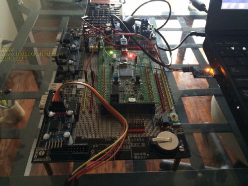
@matherp All mine FTDI went to the garbage can as I decided upgrade to 8.1 and FTDI doesn't support it under W8. I switched to CP210x and they working fine. there are some picture, the Discovery board is firmly inserted in big prototype board, there could be absolutely no Discovery board damage 
Hope that iPhone didn't flip picture upside down as happened last time Will continue with W7 Thanks Bo |
||||
| matherp Guru Joined: 11/12/2012 Location: United KingdomPosts: 11498 |
I can only suspect something about your proto board is shorting out the NRST and GND pins - this is definitely not a software issue |
||||
| boss Senior Member Joined: 19/08/2011 Location: CanadaPosts: 268 |
@matherp nope, tested NRST is working fine, fortunately I have another Discovery on its way. I plan to play with this mad one on W7 just determine what is wrong (HW or SW). Thanks Bo |
||||
| matherp Guru Joined: 11/12/2012 Location: United KingdomPosts: 11498 |
Can you unplug the Discovery from the protoboard? Then remove the shorting link SB11 on the bottom, also the two ST-LINK jumpers on the top. That will disconnect the st-link from the 407. Then just connect the RX, TX, and GND from the CP210x and the USB into CN1 to power it up. That eliminates all outside influences |
||||
| boss Senior Member Joined: 19/08/2011 Location: CanadaPosts: 268 |
@matherp I did as recommended and the result was the same then reconnect the jumpers back, erased, re-flashed and the result was same. I believe it happened when I put jumper between boot0 x VDD fleshed then probably forgot remove this jumper. 
Bo |
||||
| SteveP Newbie Joined: 21/03/2013 Location: United StatesPosts: 19 |
I am unable to produce any display on a ILI9341S device, TJCTM24024-SPI, a 2.4 TFT SPI 240*3202 using ARMmite B23. Display Open ILI9341S,1,1,2,3,240,320 makes the display dim but then commands such as CLS (white) or CLS (blue) or line (10,10,50,50,white) or DISPLAY 5,2,2,white,black,"test" do nothing. Using built-in editor, no errors. If I intentionally include bad syntax in these commands, an error does result. Display Close returns the display to its brighter intensity. Connections from the display to STM32F407 Discovery board are : VCC to 5 V GND to GND CS to PE3 (pin 2) RESET to PE4 (pin 3) D/C to PE2 (pin 1) SDI (MOSI) to PB5 (pin 91) SCK to PB3 (pin 89) LED to 5 V through 150 ohm resistor Tried 2 different display units. |
||||
| matherp Guru Joined: 11/12/2012 Location: United KingdomPosts: 11498 |
The LED pin on my display (same part number) is actually the drive to the backlight not a logic signal. I run the display at 3.3V. Use VDD from the Discovery board to connect to VCC on the display (make the shorting link J1 to bypass the regulator) and use an external power supply + 3.3V with common ground to connect to LED. I've just downloaded the b23 hex and run your exact configuration and it works perfectly for me. Just tried connecting LED direct to 3V or 5V on the Discovery - both work fine. Also try checking/replacing the D/C connection wire. I can reproduce your results if I disconnect D/C completely |
||||
| matherp Guru Joined: 11/12/2012 Location: United KingdomPosts: 11498 |
Another thought: Are you using literals "white", "red" etc? These aren't defined unless you define them e.g. const red = &Hf800 otherwise the interpreter is using these as variables that are all set to 0 i.e "black" Use OPTION EXPLICIT in every program and this will never happen!!!!!!!!!!!!!! |
||||
| Page 1 of 2 |
|||||
| The Back Shed's forum code is written, and hosted, in Australia. | © JAQ Software 2026 |
