
|
|
Forum Index : Microcontroller and PC projects : Isolated voltage sensing?
| Author | Message | ||||
| akashh Senior Member Joined: 19/01/2014 Location: IndiaPosts: 115 |
I am working on an automation system for my small recirculating hydroponic setup using a Wattmon. The idea is to have three different tanks with nutrients and acid, and dispense them automatically with small pumps when the ph or EC of the water go out of range. I purchased a ph probe and module with 0-5v output from China and that works well, but I built a TDS meter module based on a circuit off the web, and because it was a dual power supply based system I went for a voltage divider approach, so it has a 7809 regulator to step down from 12v, followed by a voltage divider to supply 4.5v to the system as ground. The op amps use this to generate a sine wave and the tds probe is part of the feedback of one of the op amps. Anyway, the point is that the tds probe puts 4.5v into the water and this messes up the ph reading completely. 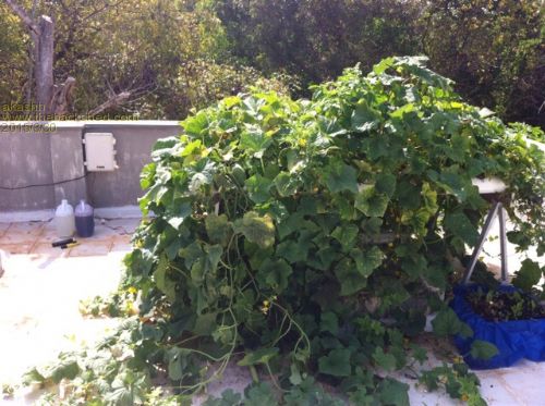
This is the system, the cistern is behind with a 12v dc pump circulating water up. The box at the back is where the automation is meant to go. I was thinking about how to isolate it and have come up with the a solution using two modules: a dc to dc converter with isolation, which steps up from 5v to 12v to power the tds circuit (us $3) , and a linear isolation module, 12v and ground on both sides, and 0-5v input one side with matching 0-5v output on the other side ($16). This would provide total isolation and hopefully solve the problem, but I will have to wait 6 weeks for them to arrive from China. Does anyone else have any experience with this and other ideas? Here are the links to the various modules: Ph module: http://www.aliexpress.com/item/PH-Sensor-PH-Value-Detection-Sensor-Module-Monitoring-Control/32261905104.html Isolated boost module: http://www.aliexpress.com/item/Regulated-DC-DC-power-supply-module-5VDC-to-12VDC-B0512S-1W-Special-factory-direct/191850 6994.html Linear isolation: http://www.aliexpress.com/item/Free-Shipping-Isolated-signal-voltage-0-5v-two-channel-linear-conversion-transmitter-modu le/1916751989.html Tds circuit based on this : http://www.octiva.net/projects/ppm/ |
||||
redrok Senior Member Joined: 15/09/2014 Location: United StatesPosts: 209 |
Hi akashh; To bad your sensors don't have digital outputs such as "Frequency", "Pulse Width Modulation" or "Duty Cycle". If they did, you could use simple isolators such as Opto Couplers or pulse transformers. MMBasic has built in commands to read this type of signal. Maybe you can find other sensors that have this type of output. Or You could role your own. The circuits to convert from analog voltage to Freq, PWM, or Duty Cycle. NE555 timer and comparator circuits come to mind. Such as this. ( I would use one of the CMOS type of 555 timer.) There are many other examples. You have one of these circuits for each analog input. It tends to be simpler to isolate the signals rather than the power supplies. Furthermore, Opto Couplers tend to be much less susceptible to noise. redrok |
||||
| robert.rozee Guru Joined: 31/12/2012 Location: New ZealandPosts: 2528 |
it looks like you are on the right track. you can get modules that take 10-16v input and output 5v on ebay (search for isolates supply). i'd be inclined to use TWO of these to get an isolated +/-5v rather than a voltage divider. if you do insist on using a voltage divider, feed this into an op-amp configured as a buffer and use the output of the op-amp as your 'ground' for somewhat better performance. the simplest way of isolating the output from everything else may be to use a micromite as an A/D converter, followed by an optocoupler driven from COM1:TxD (pin 21). this will allow you to have a small program that can do a little pre-processing of the analog signal before passing it on in digital form. cheers, rob :-) |
||||
| Zonker Guru Joined: 18/08/2012 Location: United StatesPosts: 772 |
another option... You could sent a isolated copy of the analog signal using this... We use a lot of these IC's at work on various designs... 2015-03-30_034308_ISO_Amplifier_HPCL-7800.zip Read the PDF carefully... The gain across the ISO bridge is x8 (i think) Also, Make sure the IC input voltage matches on both sides, otherwise a recieved DC offset will be included on the result side... This IC works just like you would think... It takes the analog input, and turns it into a digital serial stream, shoots it across the fence, then decodes the stream back into the analog signal.. (sweet)... It was originally designed for motor current feedback used in H Bridge PWM motor drives... Works well if designed correctly..!  |
||||
kiiid Guru Joined: 11/05/2013 Location: United KingdomPosts: 671 |
You could try with TC9402 http://rittle.org -------------- |
||||
| VK2MCT Senior Member Joined: 30/03/2012 Location: AustraliaPosts: 120 |
I think you need a -ve supply rail. If existing transformer has AC output then possibility to reconfigure to get negative rail. if existing transformer is DC out then need extra transformer to make negative rail. Could possibly use a buck convertor to create negative rail. This would allow op amps to run from + & - power rails. Sensor would then run at 0V. John B |
||||
| akashh Senior Member Joined: 19/01/2014 Location: IndiaPosts: 115 |
Thanks for all the suggestions. I think I will try and use the low cost isolated dc converter and tie the output +5v to the ground tail to generate -5v, and then as John suggested shift the circuit to ground. I was worried that the sine wave around ground would still affect readings but I will test it and report back. Zonker, that's a cool chip, thanks for the tip. Kiid it seems a bit complex to set up and one would still need a fully isolated power supply... But still a good idea. I was looking for readymade tds modules, but they are pretty expensive! Maybe a micromite with a serial calibrated output would make sense, but one could probably go for a tiny 8 bit pic with a decent adc onboard to save costs. |
||||
| The Back Shed's forum code is written, and hosted, in Australia. | © JAQ Software 2026 |
