
|
|
Forum Index : Microcontroller and PC projects : MM on my boat
| Author | Message | ||||
| ajkw Senior Member Joined: 29/06/2011 Location: AustraliaPosts: 290 |
Hi All, I thought I'd share a little of my MicroMite based project. During a fishing particular comp I participate in there is a requirement to weigh fish in alive, this needs a tank with pumps to keep the water fresh. As we also fish into the night for big fish with live baits and they (live baits) also need to be kept healthy in the same tank. My tank has a internal pump to recirculate the water and a external pump to bring in fresh water, neither pump needs to be on all the time which brings in the MicroMite. My program and hardware set up a fully adjustable auto/on/off timer that controls the pumps while for good measure I have DS18B20 (water) temp sender and a RTC to keep the time. Actually the BTT as I call it didn't get turned off for 3 days and 2 nights so at least the time will still be correct next trip. With the help and inspiration of this forum and the fantastic Maximite-Micromite platform I have expanded my abilities to -be able to get 2 micros talk to each other and finally understand those timing data/clock diagrams. (I bit banged my way into a DS1302 as my original Maximite really did need a RTC) -Write software that interfaces with LCD's, Rotary Encoders, 1 Wire, I2C, Relay Modules, RTC Modules etc etc. -Create PCB's in software on my PC and have them fabricated. Those boards out of China are fantastic compared to etching your own. -Bring the whole lot together in a box for a successful first on water test resulting in healthy fish. So thank you to those who have helped in one way or the other along the way and of course Geoff for the Maximite that got me back into programming again. Thanks also to my partner for letting me invest cash into this little project, I guess her bonus was that I was quietly busy and not annoying her. 
Cheers, Anthony. 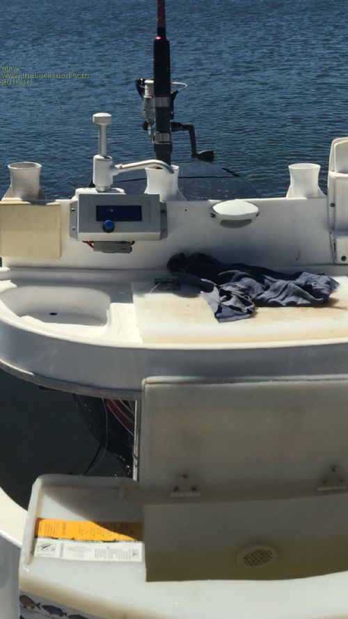
PS. I also learnt those LCD's aren't very sunlight visible. |
||||
| Geoffg Guru Joined: 06/06/2011 Location: AustraliaPosts: 3353 |
Another great project - they keep coming. You have certainly pushed the Micromite hard with so much I/O. Thanks for posting, it is inspiring to see an original and well executed idea such as this. Geoff Geoff Graham - http://geoffg.net |
||||
| twofingers Guru Joined: 02/06/2014 Location: GermanyPosts: 1732 |
Congratulations! 
For me this is almost the hardest part! Michael causality ≠ correlation ≠ coincidence |
||||
| paceman Guru Joined: 07/10/2011 Location: AustraliaPosts: 1329 |
Nice project Anthony as well as being fun, instructive and useful. Still, I think you forgot salinity, TDS, and dissolved oxygen - and of course it's great for GPS navigation too. 
You might be able to improve the brightness by using an OLED screen but they're a fair bit more expensive. Another option might be an angled shade cover (sort of verandah style) immediately above the display, glued or pop-riveted onto the box. BTW, is that fishing happening around Orford? Greg |
||||
| ajkw Senior Member Joined: 29/06/2011 Location: AustraliaPosts: 290 |
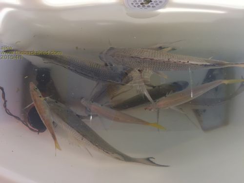
H'mmmm, I see there are dissolved oxygen sensor kits that use I2C so it wouldn't be very hard to implement but I think I will stick to looking at the fishies, if they are swimming they have oxygen. I have navigation for the boat but a GPS would be useful for the timer in order to turn off the external pump when the boat is travelling, the pick up is out of the water when planning. I have also considered a remote at the helm to set a travelling mode which would be cheaper to do and could utilise the spare I2C header. A cover would work and be easy to do particularly in regards work involved in putting it all the box. I have used every I/O on the 28pin Micromite. The I/O's are: LCD (6) ENCODER (3) DS18b20 (1) PIEZO (1) A Fet for PWM backlight (1) DS1302 RTC (3) RELAY Module (2) I2c (2) spare On the water in Port Stephens for the photo, why Orford?? Anthony. |
||||
| paceman Guru Joined: 07/10/2011 Location: AustraliaPosts: 1329 |
I wondered whether you might have been an old colleague of mine with almost the same initials who is a boating (sailing) enthusiast down at Orford - obviously not so. It's surprising what you can do with the 28 pinner isn't it. I used all but one in a timer project in this Timer thread. I have a friend who once asked me if I could make up something to display the tilt and direction angles for his stern-drive Mercruiser - prompted by more than one nasty zagging of the prop as the boat was being loaded back onto the trailer (this one weighs almost three tonnes!) I thought an absolute encoder could do the direction if you could mount it onto the steering wheel shaft but that's not easy. The tilt is a problem - anything attached to the stern-drive lives in a very nasty environment! Twofingers' comment about "putting it all in a box being the hard part" is not too far off the mark to me either. I think it's probably better to decide on the box/container before anything else. Greg |
||||
| Phil23 Guru Joined: 27/03/2016 Location: AustraliaPosts: 1667 |
I'm assuming you are not weighing them on board? Or are you already doing that with load cells & the MM. That concept would be an impressive feature. Phil. |
||||
| ajkw Senior Member Joined: 29/06/2011 Location: AustraliaPosts: 290 |
I suppose you could get a load cell small enough  Sometimes I catch them, sometimes I don't. Sometimes I catch them, sometimes I don't.The MM has been in the boat for 3 yrs now and is reliable as ever which I am happy about particularly as Greg (Paceman) mentioned, stuff in a boat is a nasty salty environment. I'll post some more detailed pic's in case somebody may be interested. Anthony. |
||||
| ajkw Senior Member Joined: 29/06/2011 Location: AustraliaPosts: 290 |
Some shameless pic's 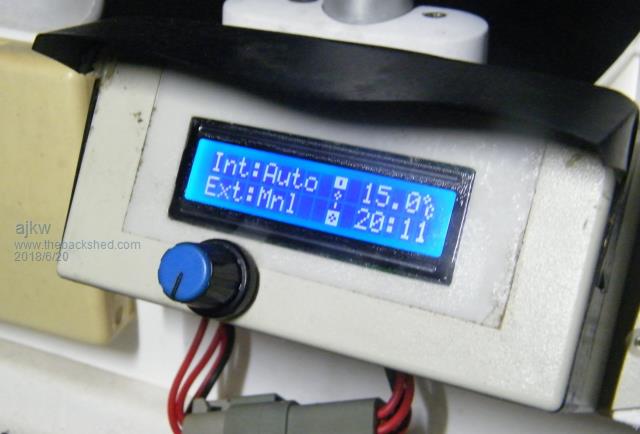 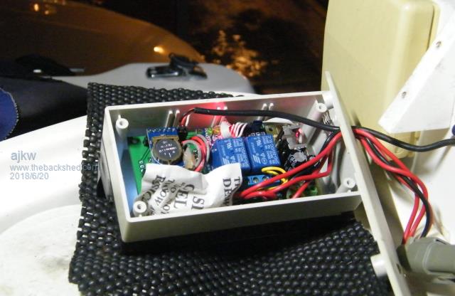 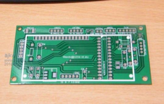 |
||||
Azure Guru Joined: 09/11/2017 Location: AustraliaPosts: 446 |
Nice work, do you have a schematic you can publish |
||||
| ajkw Senior Member Joined: 29/06/2011 Location: AustraliaPosts: 290 |
Azure, Thanks. Yeah, nah on the schematic, it is a bit, well, really ugly. The board was made with AutoTrax Dex, I was interested in the board and didn't tidy up a schematic. Pin out as follows, LCD 2,3,4,5,6,14 RTC 21,22,23 Rotary Encoder 7,9,10 DS18B20 25 Mosfet 26 (for backlight) Piezo 24 Relay 15,16 I2C 17,18 Console 11,12 Labelled Com1 ICSP 1,4,5 - I unplug the LCD for firmware upgrades. Better pic with a populated board attached. The 4 header just above the encoder wires is just a support for the LCD. 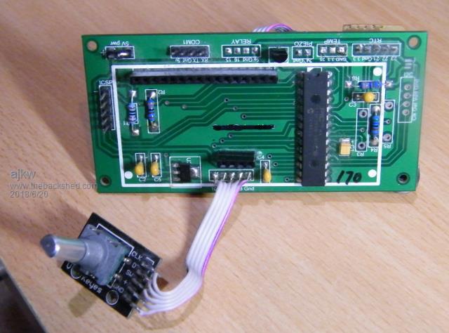 Anthony. |
||||
| Azure Guru Joined: 09/11/2017 Location: AustraliaPosts: 446 |
Very nice indeed. I studied the PCB, as best I could see it, and it all looks nice and clean. My only comment is it looks a little light on power rail caps, I did notice what looks like poly caps to reduce noise and spikes or maybe some are tantalums. I like the way you have taken the time to label the MM chip pin number on each connector pin label. With that done it is easy to get away without a schematic. Inside the case picture you posted I spotted the RTC module and relay module and what loos like a small voltage regulator board (maybe boat 12/24v down to 5v). Where they off the shelf modules or purpose built? |
||||
| ajkw Senior Member Joined: 29/06/2011 Location: AustraliaPosts: 290 |
Azure, Thanks again, I was happy with the board particularly being my first. There are some things I would change if I was to ever get another batch but I have moved onto the SMD backpack's from BigMik for subsequent projects with those nice touch screens. The RTC (DS1302 in this unit), the relay board and 12v in/5v out power supply are all off the shelf. There are caps on the 5v and 3.3v rails near the reg and 2 others on the 3.3v lines near the Pic32. The power supply has its own electro caps and interestingly I did have some noise issues on the LCD as mentioned in another current thread. A electro on the 12v supply to the bilge pump fixed that. Anthony. |
||||
| The Back Shed's forum code is written, and hosted, in Australia. | © JAQ Software 2026 |
