
|
|
Forum Index : Microcontroller and PC projects : Wireless for the Nooby revisited.
| Page 1 of 2 |
|||||
| Author | Message | ||||
| banda Newbie Joined: 12/05/2014 Location: New ZealandPosts: 35 |
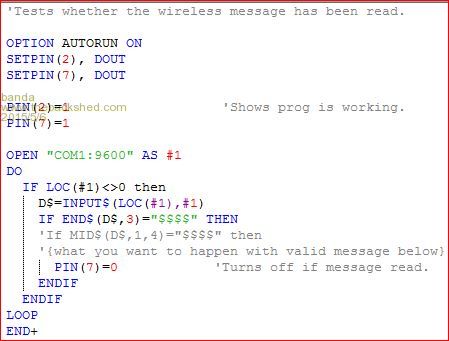
I'm back at my post again, fiddling. The prog is running. I've checked and rechecked but the green light doesn't go off. I've tried to program it so that if it has read the message the green light goes off. I've given as much info as I can, and I would appreciate if someone can tell me why the green light stays on. I'm a beginner, so I won't understand technology that's too deep, says he pitifully. 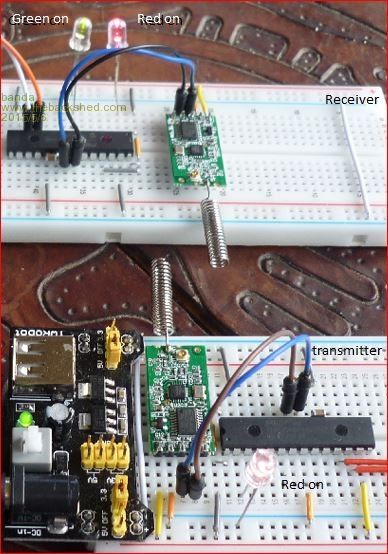
The module is an HC-11, and there is a Data Sheet, most of which I don't understand. 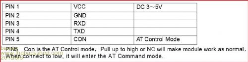
|
||||
Grogster Admin Group Joined: 31/12/2012 Location: New ZealandPosts: 9975 |
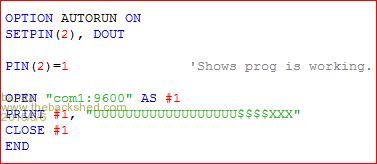
I would start by changing your END$ for something else like E$ - MMBASIC an plenty of other interpreter-type languages don't like you using keywords as variable names, and this MIGHT be the problem. You also have a + at the end of your END statement at the very end of your TX code. Other then that, I can't see anything obviously wrong, and I would expect that once the transmitter transmits, pin 7 should go low. How can you confirm(or CAN you confirm) that the RF modules are actually transmitting? Do the modules need any kind of configuration BEFORE you put them into use? Default settings of the RF module MUST match the baud-rate settings of the MM if you expect it to work. Many an RF module will have LED's on the module to indicate a TX or RX cycle. Not sure if those ones do. EDIT: Pin5 of the module must be connected to Vcc(3v3 or 5v) to put the module into normal operation. I don't see anything on pin5, assuming a left-to-right numbering arrangement. Also, remember that TXD and RXD pins swap over between ends, so that means that TXD from the MM chip, needs to go to RXD on the module, and RXD from the MM chip needs to go to TXD on the module - same at both ends of the RF link. EDIT: From what I can see, leaving pin5 on the module open is fine - that is normal mode, so ignore what I wrote above. Also, looking at your COM wires, looks correct to me, so when you transmit, you should get a transmission from the module at the TX end of things. Do you happen to have a radio scanner? EDIT: Change END$ in the loop, to MID$. The way it is currently written, the data will never match, so that is what is stopping things. You probably should also get rid of the string of U characters from the TX code, as you are using smart-modules, and they will automatically add pre-amble, so just send the data you want. Smoke makes things work. When the smoke gets out, it stops! |
||||
| Grogster Admin Group Joined: 31/12/2012 Location: New ZealandPosts: 9975 |
Try this code: RECEIVER: option autorun on setpin(2), dout setpin(7), dout pin(2)=1 pin(7)=1 open "COM1:9600" as #1 do if loc(#1)<>0 then D$=input$(loc(#1),#1) if mid$(D$,1,4)="$$$$" then 'Blah blah blah pin(7)=0 else pin(7)=1 endif endif Loop TRANSMITTER: option autorun on setpin(2), DOUT pin(2)=1 open "COM1:9600" as #1 do Print #1, "$$$$XXXX" pause 2000 loop This will send the message every 2s(as a polling transmitter arrangement), but it will help to establish the link at the other end, then you can remove the loop and just send it when you need to after you get everything working. Smoke makes things work. When the smoke gets out, it stops! |
||||
BobD Guru Joined: 07/12/2011 Location: AustraliaPosts: 935 |
This thread got me curious. As grogs said earlier, you must have the same baud rate for the Micromite and the HC-11. I did some looking up of these modules on ebay and one thing I noted was that the modules could work in a range of 1 metre to 40 metres. Less than 1 metre and they don't work. I assume the signal may be too strong and overload the receiver. A bit further looking and I found this document which banda should download and KEEP as a future reverence. Note the diagram on the top of page 2. |
||||
TassyJim Guru Joined: 07/08/2011 Location: AustraliaPosts: 6538 |
Not able to give you working code at the moment but your current code assumes that a full meif loc(#1)<>0 then D$=input$(loc(#1),#1) if mid$(D$,1,4)="$$$$" then ssage is available immediately. At 9600 baud, this is not going to happen. You need to keep receiving data and adding it onto the end of a buffer until you have a full message (or enough to start processing) Something like this: if loc(#1)<>0 then D$=input$(loc(#1),#1) buf$ = buf$+D$ if mid$(buf$,1,4)="$$$$" then ' message started ' keep recieving until end of message 'process message 'clear buffer buf$ = "" ' this might erase the start of the next message. Jim VK7JH MMedit |
||||
| Grogster Admin Group Joined: 31/12/2012 Location: New ZealandPosts: 9975 |
Jim has an EXCELLENT point there. To explain his point a little more: With the line IF LOC(#1)<>0 THEN, the problem that will happen, as Jim quite correctly is pointing out, is that as soon as there is a single byte in the buffer, the entire buffer will be read into D$, and more often then not, this will only be one byte in length(as LOC is now not equal to zero), and thus you never get four bytes to compare. TRANSMITTER CODE SNIPPET: do Print #1, "$$$$XXXX" + chr$(27) pause 2000 loop I'm using Escape(decimal 27) as the end-of-message marker, but it can be anything that is not used as a normal message. CR might not work with smart modules, as they will probably use the CR themselves to detect messages. Here is some code from my security system - this is how I build/filter and test the message data: RECEIVER FILTER CODE SNIPPET: DO IF LOC(#1)<>0 THEN DO BYTE$=INPUT$(1,#1) MSG$=MSG$+BYTE$ Loop until BYTE$=CHR$(27) OR LOC(#1)=0 IF MID$(MSG$,1,4)="$$$$" THEN PIN(7)=0 MSG$="" Endif LOOP This code sets up two loops, one running inside the other. If there is any data waiting in the serial input buffer, it is read out one byte at a time, into MSG$, and each byte is checked to see if it is the end-of-message marker(27), or that the buffer is now empty. If the qualifier does not match $$$$, then the message string is cleared, and it goes back to waiting for data again. If the message IS $$$$, then it will turn off the LED on pin 7 of the MM chip. All of this is, naturally, untested, as I don't have those modules to play with, and take heed of Bob's comment in bold - also a very valid point........ Smoke makes things work. When the smoke gets out, it stops! |
||||
| banda Newbie Joined: 12/05/2014 Location: New ZealandPosts: 35 |
I'm starting to panic now. I've tried every variation of the help I've been given but still the green light stays on. I've moved them more than a metre apart also. I've just received the new wireless pair (XY-MK-5V and FS1000A), so I tried them . I just replaced the HC-11 pair and connected the new ones as in the photo. In the receiver I connected the data pin to Rx and the Transmitter data pin to Tx. The green light stayed on. I then connected them on the other way. The green light still stayed on. Having no Rx and Tx pins on the modules gave me much cause to pause and wonder. I do admit to not having antennae on, but the built-in antennae are only 5 cm apart and my reading gave me hope that it should work. As well, 3 volts will apparently work on the short separation. I'm still hoping that someone has built either of the two makes of wireless so I can follow their construction, or at least find where I'm making a boo-boo. Who'd have thought that Micromite would be so involved? (Or me so dumb?) 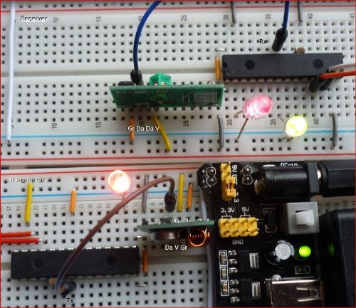
|
||||
| Grogster Admin Group Joined: 31/12/2012 Location: New ZealandPosts: 9975 |
Now that you have swapped modules to dumb ones, you will need the preamble back - the series of U's to sync the data-slicer in the receiver module. You did not need them for the first type of modules, as smart-modules take care of all that side of things for you. Cheap modules like the ones you are using now also should not really be run any faster then 2400 baud - 9600 baud is probably pushing it for those modules. 
With the cheapies, there is no TXD and RXD pins, they are normally just labelled as "DATA", which on the transmitter module is the data input pin - goes to TXD on the MM chip, and "DATA" on the receiver module is the data out of the module, and usually is two separate pins, but either/or/both are the same connection - goes to RXD on the MM chip. Setup the following code on your TRANSMITTER MM chip: Open "COM1:2400" as #1 DO Print #1, "UUUUUUUUUU$$$$XXXX" + CHR$(27) Pause 2500 LOOP ...and setup the following code on your RECEIVER MM chip: DO IF LOC(#1)<>0 THEN DO BYTE$=INPUT$(1,#1) MSG$=MSG$+BYTE$ Loop until BYTE$=CHR$(27) OR LOC(#1)=0 IF MID$(MSG$,1,4)="$$$$" THEN PIN(7)=0 PAUSE 1000 PIN(7)=1 ENDIF MSG$="" Endif LOOP That SHOULD setup a situation, where the transmitter will transmit bursts of the message to the receiver over and over, with a 2.5s delay between cycles, and the receiver - when it gets the message, will turn the LED on pin-7 off for 1s then turn it back on again for the next time. EDIT: It is neither one. The MM is not involved(quite the opposite compared to other platforms!), and you are not dumb either. TIME is the factor here. It took me years to know what I know now, and working with serial comms is a bit of a nightmare for many hobbyists who are new to it. I do lots of serial work, so PM me if you would like to send me the modules, and I will get them working, and send them back with sample codes for you to try out. Smoke makes things work. When the smoke gets out, it stops! |
||||
| BobD Guru Joined: 07/12/2011 Location: AustraliaPosts: 935 |
Banda In these forums in recent times there have been several very difficult to solve problems. The cause has been breadboards that didn't make contact properly. I'm not sure of the exact cause but it was something like the sockets in the breadboard were too deep. Someone who knows exactly might tell us. Just make sure that all of your components on the breadboard are making contact. Bob |
||||
| WhiteWizzard Guru Joined: 05/04/2013 Location: United KingdomPosts: 2991 |
Hi Barry, From your photos above you appear to be driving the LEDs directly from the MicroMite pins. This is NOT good if you are using 'standard' LEDs (i.e. ones without built in current limiting resistors). You need to put a single resistor either side of the LED. I prefer to use a resistor between the PIC pin and the LED (rather than between the LED and GND). You may have damaged any outputs if excess current has been pulled due to the 'missing' current limiting resistor. Ideally when driving an LED with a '1' (high) you want to keep current flowing from the pin below 15mA. Use a resistor around 100ohms (but anything unto 1k will do for testing). The higher the value, the dimmer the LED will 'glow'. To test if there is any damage, write a simple 'blink' program to test the pin (i.e. test Pin 7 with an LED AND resistor) Hope this helps . . . WW |
||||
| WhiteWizzard Guru Joined: 05/04/2013 Location: United KingdomPosts: 2991 |
I am sure you're an 'expert' by now with the code to flash/test an LED. But in case you need it . . . . SETPIN(7),DOUT DO PIN(7)=1 PAUSE 250 PIN(7)=0 PAUSE 250 LOOP EDIT: Remember to ADD a series resistor in line with the LED |
||||
bigmik Guru Joined: 20/06/2011 Location: AustraliaPosts: 2981 |
Hi Bob, All, I can concur with that, Have a read of my fun and games in An embarrassing Saga.. I believe I fell victim of wonky a breadboard... Regards, Mick Mick's uMite Stuff can be found >>> HERE (Kindly hosted by Dontronics) <<< |
||||
| HankR Senior Member Joined: 02/01/2015 Location: United StatesPosts: 209 |
Won't the MID$(MSG$,1,4)= "$$$$" test fail to detect a "light off" command if one or more of the serial transmitted U characters are included in the assembled valid message string? It seems as if just one of those U characters is recognized as valid serial data, the LED will never turn off. There are a few ways to test for the "$$$$" string in the presence of any preceding U characters. |
||||
| Grogster Admin Group Joined: 31/12/2012 Location: New ZealandPosts: 9975 |
Possible. I have NEVER had that - EVER. Mind you, I use Radiometrix modules that cost about US$20 each - for the dumb ones, so they are about 20x the price per unit, of the cheap Chinese ones, and for that extra cash, they do exactly as advertised, so they most likely have a MUCH better data-slicer arrangement then the cheapies. I guess you could try the likes of a PAUSE one or two ms in between sending the U's and the data, but I have never needed to. I have hundreds of transmitters in service now, all using this concept, and they have never missed a single byte of the wanted data. HOWEVER, having said all that, high-quality RF transmitter/receiver pairs that have been lab-tested and approved by Government agencies will be of a much better quality then the $1 units - C'est La Vie - so the U's idea may have issues with the cheapies, although the theory as to why to do it is still sound.
EDIT: Oh wait a minute..... You might have something there, Hank. 
All my receivers use PICAXE units, and they WAIT for the prescribed data to arrive. In my system, I use a PICAXE-08 to act as a data-filter. It listens to the receiver all the time, waiting for the qualifier. Once it sees that, it then reads the rest of the message bytes, and forwards just those over to the main processor unit. Excrement - I may have been putting Banda a little wrong here - will look into this a bit more and post back. Smoke makes things work. When the smoke gets out, it stops! |
||||
| HankR Senior Member Joined: 02/01/2015 Location: United StatesPosts: 209 |
The above explanation makes all the difference in the world! I think this one line change to your suggested code for testing the message string may be the ticket: IF INSTR(1,MSG$,"$$$$") <> 0 THEN |
||||
| HankR Senior Member Joined: 02/01/2015 Location: United StatesPosts: 209 |
Barry, I'd encourage you to use liberal use of print statements in debugging your programs. This wireless program is overdue for some print statements that establish that you're even getting any wireless serial communication taking place at all. That needs to be confirmed first before going much further with efforts to get the control signal recognition part working. Here is just a suggestion of adding some prints that should shed some light on what's going on. It's a matter of going back to basics and getting something going right instead of just trying to get the whole program working while being totally in the dark about what's at fault. Hope you can try something like this and report what happened. I've used the dumb modules before, but only with the special pulse coding that's more common. I'd like to explore using regular serial, and I'm also thinking of getting a pair of HC-11 modules and trying those. Hank DO IF LOC(#1)<>0 THEN DO BYTE$=INPUT$(1,#1) MSG$=MSG$+BYTE$ INDEX = INDEX + 1 PRINT INDEX PRINT MSG$ LOOP UNTIL BYTE$=CHR$(27) OR LOC(#1)=0 PRINT MSG$ IF INSTR(1, MSG$,"$$$$") <> 0 THEN PRINT "RECOGNIZED CODE: " + MSG$ PIN(7)=0 PAUSE 1000 PIN(7)=1 ENDIF MSG$="" INDEX = 0 ENDIF LOOP |
||||
| Justplayin Guru Joined: 31/01/2014 Location: United StatesPosts: 330 |
Have you verified your setup (software and hardware) function without the radio modules installed? I'd try to directly connect the two COM ports to make sure the basic hardware and software configuration is working, then add the radio modules back into the equation. Just a thought... --Curtis I am not a Mad Scientist... It makes me happy inventing new ways to take over the world!! |
||||
| banda Newbie Joined: 12/05/2014 Location: New ZealandPosts: 35 |
Talk about being born unto trouble, that's me. Right from the beginning of my study of Micromite I've got into trouble and have had to ask help to get me out. Bobd has pointed out the iffyness of breadboards. Very early on I had to be helped out of that one, so now I take painstaking effort to try to check that contacts are working. Phil (Hi Phil  ), has pointed out that I should use resistors with my LEDs. I haven't because every new connection I make adds a chance of bad contacts, and surprisingly to me, not having resistors seems to work. When the program doesn't do what it's meant to, I check that the LEDs are able to work. So far they seem to behave. ), has pointed out that I should use resistors with my LEDs. I haven't because every new connection I make adds a chance of bad contacts, and surprisingly to me, not having resistors seems to work. When the program doesn't do what it's meant to, I check that the LEDs are able to work. So far they seem to behave.
Grogster has shown me time and time again how little I know, and has kindly smoothed over my ignorance. Time and again he's put me on the right track. HankR has uncovered an esoteric area of procedure that is well past the page 7 I'm on. His logic seems faultless to me. I've just seen that he has given me further advice, but I'll send this first, then tackle his note. Those people and many others have tried to help me out of trouble. However, I still can't get the damn thing to work. Apparently nobody on earth has made a pair of HC-11s connect via Micromite. Apparently nobody on earth has made an FS1000A talk to an XY-MK-5V via Micromite. But all is not lost. Grogster has asked for, and I have sent, 2 HC-11s to him. He could be the first person in all civilized society to make 2 HC-11s communicate via Micromite. Thanks to you all. The error is probably mine, but at least I'll find out. I can hope that breastbeating is therapeutic. |
||||
| viscomjim Guru Joined: 08/01/2014 Location: United StatesPosts: 925 |
Hi Banda, I started just like you, no experience with uMite at all. In fact started with the beta of the first uMite. Pulled a lot of my hair out, but sticking with it and the good folks here at TBS, I have had great success with many cool projects. I encourage you to keep trying, it WILL BE worth it!!! I would definitely try the suggestion from Justplayin and tie the two uMites together with wires and get that to work first, then throw the radios in the mix. Good luck!!!! |
||||
Bryan1 Guru Joined: 22/02/2006 Location: AustraliaPosts: 2092 |
Hi Guy's, This thread has given me some good info so last night had a look thru my electronic gear and found the 3 pair of rx/tx modules I have here. All came from Oatleys a few years ago and are still new. Anyway as it has been years since I played with them silly me forgot the antenna length so went for a bit of a search and found a good read on antenna design. Also found an old 28 pin board I made up for Nigel's tutorials years ago on perf board so going to transform that to suit the 170 chip with a rx/tx pair. Regards Bryan |
||||
| Page 1 of 2 |
|||||
| The Back Shed's forum code is written, and hosted, in Australia. | © JAQ Software 2026 |
