Chris Roper
Senior Member

Joined: 19/05/2015
Location: South AfricaPosts: 280 |
| Posted: 05:16am 29 May 2015 |
 Copy link to clipboard Copy link to clipboard |
 Print this post |
|
Yesterday I mentioned the project that I am working on and a couple of people were keen to know more, so here is the first instalment.
The basic idea is to build one of Geoff's ASCII controllers into a Keyboard and plug the hole with a breadboard.
But I didn't want any old breadboard. I wanted a breadboard that gave the flexibility and features needed to develop complex applications, on a variety of platforms, yet be uncluttered, compact and user friendly.
It should be accessible to beginners in order to teach basic electronics as well as provide an introduction to Programming, and in that role it should be easier to use than the Arduino (or other such boards) and preferably be self contained and portable.
For advanced users I wanted it to be capable of rudimentary product testing, generating inputs to the device under test and reading outputs to confirm correct operation and speed up debugging.
To meet the above requirements I chose the MicroMite II. With its integrated Editor / Interpreter combination and the PIC32MX core it can easily meet the basic Training requirement as well as being easy to create custom Test and Measurement code for debugging other projects.
Part One - Breadboard
The Breadboard is based on my experience of breadboarding for a variety of Product Families. But rather than try and include everything that could possibly be needed I have taken a minimalist approach and incorporated only the bare essentials but augmented it with flexible expansion capability. That way you only need to connect the modules that are relevant to your current project, rather than have a single board that takes up most of your desk or workbench.
It also meant that I could incorporate it into the Keyboard to make an integrated, portable system without hookup wires strung all over the place.
Here are two shots of an early prototype:
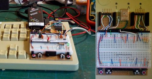
The first in use testing the ASCII Controller / MicroMite II combination and the second a top down view. (excuse the bad photo's, it is winter here in Cape Town and I have bad light).
The secret to flexibility, and the longest part of the development cycle so far, is the choice of connectors and their function. The picture below is the key to what follows:
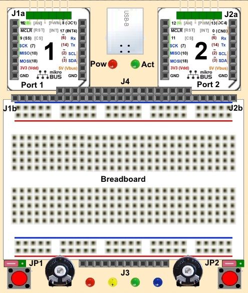
J1a/J1b and J2a/J2b are straight through, one to one, connections and act as generic ports to dock ICSP, USB Serial Converters, Test Instruments etc. The Picture of the prototype has a PICKit 2, acting as a Power Supply and Logic Tool connected to J1a and a USB to Serial Board connected to J2a. The Auxiliary USB port, situated between them, is connected from the ASCII terminal controller Chip to the PC. The white cable is the Keyboards Power and Data lines which will be routed internally in the final design.
J3 provides the Minimum I/O accessory's needed in every project, two push buttons, two POT's and four LED's. JP1 and JP2 are used to set PB1 and PB2 as active Low or active high. J3 also routes Gnd, 3V3 and 5V power connections to the bottom of the breadboard to eliminate the need for long bridge links (as seen in the photo's) and facilitate split power buses.
J4 is the heart of the system and is connected internally to the MicroMite II (Or other CPU Board) bringing all of the Pins out to the Breadboard edge. The Pins are grouped by function, as opposed to package, and sockets are also provided for Power, Auxiliary USB, The ASCII Terminal / Console Connections etc.
The Final Connectors comprise two expansion Ports that conform to the mikroBUS Standard. I chose mikroBUS as a standard prototyping bus several years ago and am pleased to see other Development Board manufacturers have started to do the same. The standard requires an article on its own but suffice it to say that this BUS can now be found on Arduino Clones, Beagle Bone Boards and several other 3rd Party CPU boards along with Large development boards such as the EASYPic range.
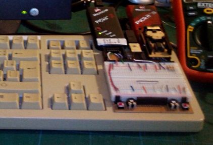
Hundreds of modules, ranging from WiFi to GSM and GPS, as well as simple LED Bar-graph and Rotary encoder boards are now available to plug in to it. And the form factor makes it easy to design your own modules on VIRO Board. The Photo above shows a PICKit 2 and a PICKit 3 connected to the ISCP ports and a home made RTC Module plugged into the microBUS 2 Port.
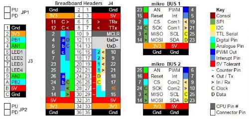
Finally here is the PIN Map showing how everything is connected:
In a future post I will describe the mikroBUS in greater detail and then the actual CPU's installed inside the Keyboard, but for now I hope this gives others an insight into how to design/build your own flexible Development Breadboard.
Cheers for now......
Chris
EDITS: Spelling
Edited by Chris Roper 2015-05-30
http://caroper.blogspot.com/ |
