
|
|
Forum Index : Microcontroller and PC projects : MM2: The Micromite can see:-)
| Author | Message | ||||
| matherp Guru Joined: 11/12/2012 Location: United KingdomPosts: 10247 |
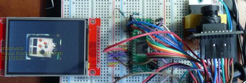
Only QQVGA (160x120) as that fills the Micromite memory. This version of the camera doesn't have a FIFO so the image is buffered in the Micromite memory and then written out to the display. I need to tidy up the code and will post it as a follow up ASAP I'm getting about 10fps running on a 44-pin part at 48MHz. The code won't run on a 28-pin processor as it needs a dedicated 8-bit port to transfer the image data in from the camera. |
||||
| WhiteWizzard Guru Joined: 05/04/2013 Location: United KingdomPosts: 2933 |
Nice one Peter. If this develops at anything like the speed your TFT work developed then I suggest everyone waits until next week by which time you will be having a working HD camera  (or two weeks for 4K cameras). (or two weeks for 4K cameras).
Purely out of interest, can you link to the type of camera you have used here! 
Can't wait to see people's responses to this line of development . . . . WW |
||||
| matherp Guru Joined: 11/12/2012 Location: United KingdomPosts: 10247 |
This one doesn't have the onboard FIFO. This one does. Current code only works with the first version but once I have one of the others it will be possible to get full VGA working |
||||
bigmik Guru Joined: 20/06/2011 Location: AustraliaPosts: 2949 |
Peter, Another fantastic advancement you have made... Any chance of creating some sun in Fiji for the last two days of my holiday? Thought I would ask you seem to be a miracle worker these days.. Mik Mick's uMite Stuff can be found >>> HERE (Kindly hosted by Dontronics) <<< |
||||
| matherp Guru Joined: 11/12/2012 Location: United KingdomPosts: 10247 |
Here is the code and wiring details. Note that during each camera input routine (about 25msecs) the RTC has to be stopped to avoid missing data so the time will be incorrect unless a subsequent call to RTC GETTIME is used. The camera has 200+ registers that can be set. The attached code sets up my camera to give a reasonable display but feel free to play with the initialisation, you could spend many happy? hours on this
There is one camera specific CFunction (44-pin part only) and three general purpose Cfunctions (can also be used on 28-pin parts) General purpose routines: Turn on a clock output: clockon(n) This routine uses the PIC hardware to output a free-running clock signal on one of the pins. The speed of the clock can be set using the single parameter n is the divider of the system clock so specifying CPU 48 and n=6 gives an output clock of 8MHz the clock is always on pin 15 of a 28-pin part and pin 42 of a 44-pin part the routine will automatically set up the pin as a digital output Turn off a clock output:clockoff the clock is always on pin 15 of a 28-pin part and pin 42 of a 44-pin part the pin will be released to the available pool by the clockoff function Display RGB565 bitmap: DisplayBitmap(cspin,dcpin,buffer(),x,y,w,h) This routine outputs a full colour bitmap to the display initialised by OPTION LCDPANEL. cspin: pin connected to CS on the display dcpin: pin connected to D/C on the display buffer: integer array containing pixels to display in packed RGB565 format so there must be 4 x 16-bit pixels in each array element x coordinate of top left of screen area to display the bitmap y coordinate of top left of screen area to display the bitmap width of screen space to display bitmap height of scren space to display bitmap Camera Specific: Initialise the camera: ov7670init(n) n is optional and selects the mode; 0 or missing selects normal operation 1-3 selects colour bars as per the ov7670 datasheet the camera works in QQVGA mode 160 x 120 pixels, RGB565 the init routine contains a full set of register definitions to allow the user to make changes as required there are three supporting routines to set up the camera ov7670set(reg,value) set register reg to value val does a read after write to confirm the update ov7670mod(reg,value) set bits in register reg according to value val does a read before write to get the current value and then ORs the input before writing the register with the replacement value ov7670clr(reg,value) clears bits in register reg according to value val does a read before write to get the current value and then ANDs the complement of the input before writing the register with the replacement value The camera only works on the 44-pin part and uses the following fixed pinout: 3V3 - connect to +V : GND connect to GND SIOC - connect to I2C Clock pin 44 : SIOD connect to I2CDATA pin 1 VSYNCH - connect to pin 19 : HREF connect to pin 4 PCLK - connect to pin 5 : XCLK connect to pin 42 D7 - connect to pin 3 : D6 - connect to pin 2 D5 - connect to pin 38 : D4 - connect to pin 37 D3 - connect to pin 36 : D2 - connect to pin 27 D1 - connect to pin 26 : D0 - connect to pin 25 RESET - connect to display reset : PWDN - connect to +V The full code is: option default none option explicit ' ' turn on a clock output: clockon(n) ' n is the divider of the system clock so specifying CPU 48 and n=6 gives an output clock of 8MHz ' the clock is always on pin 15 of a 28-pin part and pin 42 of a 44-pin part ' the routine will automatically set up the pin as a digital output ' ' turn off a clock output: clockoff ' the clock is always on pin 15 of a 28-pin part and pin 42 of a 44-pin part ' the pin will be released to the available pool by the clockoff function ' ' Display RGB565 bitmap: DisplayBitmap(cspin,dcpin,buffer(),x,y,w,h) ' cspin: pin connected to CS on the display ' dcpin: pin connected to D/C on the display ' buffer: integer array containing pixels to display in packed RGB565 format ' so there must be 4 x 16-bit pixels in each array element ' x coordinate of top left of screen area to display the bitmap ' y coordinate of top left of screen area to display the bitmap ' width of screen space to display bitmap ' height of scren space to display bitmap ' ' Initialise the camera: ov7670init(n) ' n is optional and selects the mode 0 or missing selects normal operation ' 1-3 selects colour bars as per the ov7670 datasheet ' the camera works in QQVGA mode 160 x 120 pixels, RGB565 ' the init routine contains a full set of register definitions to allow the user to make changes as required ' there are three supporting routines to set up the camera ' ov7670set(reg,value) ' set register reg to value val ' does a read after write to confirm the update ' ov7670mod(reg,value) ' set bits in register reg according to value val ' does a read before write to get the current value and then ORs the input ' before writing the register with the replacement value ' ov7670clr(reg,value) ' clears bits in register reg according to value val ' does a read before write to get the current value and then ANDs the complement of the input ' before writing the register with the replacement value ' The camera only works on the 44-pin part and uses the following fixed pinout: ' 3V3 - connect to +V : GND connect to GND ' SIOC - connect to I2C Clock pin 44 : SIOD connect to I2CDATA pin 1 ' VSYNCH - connect to pin 19 : HREF connect to pin 4 ' PCLK - connect to pin 5 : XCLK connect to pin 42 ' D7 - connect to pin 3 : D6 - connect to pin 2 ' D5 - connect to pin 38 : D4 - connect to pin 37 ' D3 - connect to pin 36 : D2 - connect to pin 27 ' D1 - connect to pin 26 : D0 - connect to pin 25 ' RESET - connect to display reset : PWDN - connect to +V ' DIM INTEGER i ' cpu 48 i=clockon(6) ' START A 8mhZ CLOCK on pin 42 ov7670init cls do i=ReadCamera(ov7670_buffer()) if i=ov7670_wi*ov7670_ht*2 then i=DisplayBitmap(15, 12, ov7670_buffer(), 80, 60, 160, 120) loop end ' sub ov7670_set(a as integer, b as integer) local c% i2c write ov7670_address,0,2,a,b if a=REG_COM7 and b=COM7_RESET then exit sub i2c write ov7670_address,0,1,a pause 2 i2c read ov7670_address,0,1,c% if b<>c% then print "Parameter load error" end sub ' sub ov7670_mod(a as integer, b as integer) local c% i2c write ov7670_address,0,1,a pause 2 i2c read ov7670_address,0,1,c% c% = c% OR b i2c write ov7670_address,0,2,a,c% end sub ' sub ov7670_clr(a as integer, b as integer) local c% i2c write ov7670_address,0,1,a pause 2 i2c read ov7670_address,0,1,c% c% = c% AND (NOT b) i2c write ov7670_address,0,2,a,c% end sub ' sub ov7670init(mode%) const REG_GAIN =&H00 ' Gain lower 8 bits (rest in vref const REG_BLUE =&H01 ' blue gain const REG_RED =&H02 ' red gain const REG_VREF =&H03 ' Pieces of GAIN, VSTART, VSTOP const REG_COM1 =&H04 ' Control 1 const COM1_CCIR656 =&H40 ' CCIR656 enable const REG_BAVE =&H05 ' U/B Average level const REG_GbAVE =&H06 ' Y/Gb Average level const REG_AECHH =&H07 ' AEC MS 5 bits const REG_RAVE =&H08 ' V/R Average level const REG_COM2 =&H09 ' Control 2 const COM2_SSLEEP =&H10 ' Soft sleep mode const REG_PID =&H0a ' Product ID MSB const REG_VER =&H0b ' Product ID LSB const REG_COM3 =&H0c ' Control 3 const COM3_SWAP =&H40 ' Byte swap const COM3_SCALEEN =&H08 ' Enable scaling const COM3_DCWEN =&H04 ' Enable downsamp/crop/window const REG_COM4 =&H0d ' Control 4 const REG_COM5 =&H0e ' All "reserved" const REG_COM6 =&H0f ' Control 6 const REG_AECH =&H10 ' More bits of AEC value const REG_CLKRC =&H11 ' Clocl control const CLK_EXT =&H40 ' Use external clock directly const CLK_SCALE =&H3f ' Mask for internal clock scale DIM integer REG_COM7 =&H12 ' Control 7 DIM integer COM7_RESET =&H80 ' Register reset const COM7_FMT_MASK =&H38 ' const COM7_FMT_VGA =&H00 ' VGA format const COM7_FMT_CIF =&H20 ' CIF format const COM7_FMT_QVGA =&H10 ' QVGA format const COM7_FMT_QCIF =&H08 ' QCIF format const COM7_RGB =&H04 ' bits 0 and 2 - RGB format const COM7_YUV =&H00 ' YUV const COM7_BAYER =&H01 ' Bayer format const COM7_PBAYER =&H05 ' "Processed bayer" const COM7_COLOR_BAR =&H02 ' Enable Color Bar const REG_COM8 =&H13 ' Control 8 const COM8_FASTAEC =&H80 ' Enable fast AGC/AEC const COM8_AECSTEP =&H40 ' Unlimited AEC step size const COM8_BFILT =&H20 ' Band filter enable const COM8_AGC =&H04 ' Auto gain enable const COM8_AWB =&H02 ' White balance enable const COM8_AEC =&H01 ' Auto exposure enable const REG_COM9 =&H14 ' Control 9 - gain ceiling const REG_COM10 =&H15 ' Control 10 const COM10_HSYNC =&H40 ' HSYNC instead of HREF const COM10_PCLK_HB =&H20 ' Suppress PCLK on horiz blank const COM10_HREF_REV =&H08 ' Reverse HREF const COM10_VS_LEAD =&H04 ' VSYNC on clock leading edge const COM10_VS_NEG =&H02 ' VSYNC negative const COM10_HS_NEG =&H01 ' HSYNC negative const REG_HSTART =&H17 ' Horiz start high bits const REG_HSTOP =&H18 ' Horiz stop high bits const REG_VSTART =&H19 ' Vert start high bits const REG_VSTOP =&H1a ' Vert stop high bits const REG_PSHFT =&H1b ' Pixel delay after HREF const REG_MIDH =&H1c ' Manuf. ID high const REG_MIDL =&H1d ' Manuf. ID low const REG_MVFP =&H1e ' Mirror / vflip const MVFP_MIRROR =&H20 ' Mirror image const MVFP_FLIP =&H10 ' Vertical flip const REG_AEW =&H24 ' AGC upper limit const REG_AEB =&H25 ' AGC lower limit const REG_VPT =&H26 ' AGC/AEC fast mode op region const REG_HSYST =&H30 ' HSYNC rising edge delay const REG_HSYEN =&H31 ' HSYNC falling edge delay const REG_HREF =&H32 ' HREF pieces const REG_TSLB =&H3a ' lots of stuff const TSLB_YLAST =&H04 ' UYVY or VYUY - see com13 const TSLB_UV =&H10 ' enable special effects const TSLB_NEGATIVE =&H20 ' enable special effects const REG_COM11 =&H3b ' Control 11 const COM11_NIGHT =&H80 ' Night mode enable const COM11_NIGHT_FR2 =&H20 ' Night mode 1/2 of normal framerate const COM11_NIGHT_FR4 =&H40 ' Night mode 1/4 of normal framerate const COM11_NIGHT_FR8 =&H60 ' Night mode 1/8 of normal framerate const COM11_HZAUTO =&H10 ' Auto detect 50/60 Hz const COM11_50HZ =&H08 ' Manual 50Hz select const COM11_EXP =&H02 ' Exposure timing can be less than limit const REG_COM12 =&H3c ' Control 12 const COM12_HREF =&H80 ' HREF always const REG_COM13 =&H3d ' Control 13 const COM13_GAMMA =&H80 ' Gamma enable const COM13_UVSAT =&H40 ' UV saturation auto adjustment const COM13_UVSWAP =&H01 ' V before U - w/TSLB const REG_COM14 =&H3e ' Control 14 const COM14_DCWEN =&H10 ' DCW/PCLK-scale enable const COM14_MAN_SCAL =&H08 ' Manual scaling enable const COM14_PCLK_DIV1 =&H00 ' PCLK divided by 1 const COM14_PCLK_DIV2 =&H01 ' PCLK divided by 2 const COM14_PCLK_DIV4 =&H02 ' PCLK divided by 4 const COM14_PCLK_DIV8 =&H03 ' PCLK divided by 8 const COM14_PCLK_DIV16 =&H04 ' PCLK divided by 16 const REG_EDGE =&H3f ' Edge enhancement factor const REG_COM15 =&H40 ' Control 15 const COM15_R10F0 =&H00 ' Data range 10 to F0 const COM15_R01FE =&H80 ' 01 to FE const COM15_R00FF =&Hc0 ' 00 to FF const COM15_RGB565 =&H10 ' RGB565 output const COM15_RGB555 =&H30 ' RGB555 output const COM15_RGB444 =&H10 ' RGB444 output const REG_COM16 =&H41 ' Control 16 const COM16_AWBGAIN =&H08 ' AWB gain enable const COM16_DENOISE =&H10 ' Enable de-noise auto adjustment const COM16_EDGE =&H20 ' Enable edge enhancement const REG_COM17 =&H42 ' Control 17 const COM17_AECWIN =&Hc0 ' AEC window - must match COM4 const COM17_CBAR =&H08 ' DSP Color bar const REG_DENOISE_STRENGTH =&H4c ' De-noise strength const REG_SCALING_XSC =&H70 const REG_SCALING_YSC =&H71 const REG_SCALING_DCWCTR =&H72 const REG_SCALING_PCLK_DIV =&H73 const REG_SCALING_PCLK_DELAY =&Ha2 ' QQVGA setting const COM7_QQVGA =&H00 const HSTART_QQVGA =&H16 const HSTOP_QQVGA =&H04 const HREF_QQVGA =&Ha4 '=&H24? =&Ha4? const VSTART_QQVGA =&H02 const VSTOP_QQVGA =&H7a const VREF_QQVGA =&H0a const COM3_QQVGA =&H04 const COM14_QQVGA =&H1A const SCALING_XSC_QQVGA =&H3a const SCALING_YSC_QQVGA =&H35 const SCALING_DCWCTR_QQVGA =&H22 const SCALING_PCLK_DIV_QQVGA =&Hf2 const SCALING_PCLK_DELAY_QQVGA =&H02 const REG_CMATRIX_BASE =&H4f const REG_CMATRIX_1 =&H4f const REG_CMATRIX_2 =&H50 const REG_CMATRIX_3 =&H51 const REG_CMATRIX_4 =&H52 const REG_CMATRIX_5 =&H53 const REG_CMATRIX_6 =&H54 const CMATRIX_LEN = 6 const REG_CMATRIX_SIGN =&H58 ' const REG_BRIGHT =&H55 ' Brightness const REG_CONTRAST =&H56 ' Contrast control const REG_GFIX =&H69 ' Fix gain control const REG_GGAIN =&H6a ' G channel AWB gain const REG_DBLV =&H6b ' PLL control const REG_REG76 =&H76 ' OV's name const R76_BLKPCOR =&H80 ' Black pixel correction enable const R76_WHTPCOR =&H40 ' White pixel correction enable const REG_RGB444 =&H8c ' RGB 444 control const R444_ENABLE =&H02 ' Turn on RGB444, overrides 5x5 const R444_RGBX =&H01 ' Empty nibble at end const R444_XBGR =&H00 const REG_HAECC1 =&H9f ' Hist AEC/AGC control 1 const REG_HAECC2 =&Ha0 ' Hist AEC/AGC control 2 const REG_BD50MAX =&Ha5 ' 50hz banding step limit */ const REG_HAECC3 =&Ha6 ' Hist AEC/AGC control 3 */ const REG_HAECC4 =&Ha7 ' Hist AEC/AGC control 4 */ const REG_HAECC5 =&Ha8 ' Hist AEC/AGC control 5 */ const REG_HAECC6 =&Ha9 ' Hist AEC/AGC control 6 */ const REG_HAECC7 =&Haa ' Hist AEC/AGC control 7 */ const REG_BD60MAX =&Hab ' 60hz banding step limit */ dim integer ov7670_wi=160, ov7670_ht=120, ov7670_address=&h21, ov7670_buffer(4800) setpin 25,din: setpin 26,din: setpin 27,din: setpin 36,din: setpin 37,din: setpin 38,din setpin 2,din: setpin 3,din: setpin 4,din: setpin 5,din 'set port C as inputs setpin 19,DIN ' input clock pulse i2c open 100,1000 ov7670_set(REG_COM7,&H80) 'set to default settings pause 1000 ov7670_set(REG_COM7, COM7_QQVGA OR COM7_RGB) if mode% then ov7670_set(REG_COM7, COM7_COLOR_BAR) ov7670_set( REG_CLKRC, &H81 ) ov7670_set( REG_RGB444, 0 ) ov7670_set( REG_COM1, 0) ov7670_set( REG_COM15, COM15_R00FF OR COM15_RGB565) ov7670_mod(REG_COM9, &H38) ov7670_set(&H4F,&Hb3) ov7670_set(&H50, &Hb3 ) ov7670_set(&H51, 0 ) ov7670_set(&H52, &H3d ) ov7670_set(&H53, &Ha7 ) ov7670_set(&H54, &He4 ) ov7670_set(REG_COM13, COM13_GAMMA OR COM13_UVSAT ) ov7670_set(REG_HSTART,&H16) ov7670_set(REG_HSTOP, &H04) ov7670_set(REG_HREF, &H24) ov7670_set(REG_VSTART, &H02) ov7670_set(REG_VSTOP, &H7a) ov7670_set(REG_VREF, &H0a) 'scaling ov7670_set(REG_COM3, COM3_QQVGA) ov7670_set(REG_COM14, COM14_QQVGA) ov7670_set(REG_SCALING_XSC, SCALING_XSC_QQVGA ) ov7670_set(REG_SCALING_YSC, SCALING_YSC_QQVGA) ov7670_set(REG_SCALING_DCWCTR, SCALING_DCWCTR_QQVGA) ov7670_set(REG_SCALING_PCLK_DIV, SCALING_PCLK_DIV_QQVGA) ov7670_set(REG_SCALING_PCLK_DELAY, SCALING_PCLK_DELAY_QQVGA) if mode% and 1 then ov7670_mod(REG_SCALING_XSC, &H80) if mode% and 2 then ov7670_mod(REG_SCALING_YSC, &H80) ov7670_set(REG_COM5, &H61 ): ov7670_set(REG_COM6, &H4b) ov7670_set(&H16, &H02 ): ov7670_set( REG_MVFP, &H07) ov7670_set(&H21, &H02 ): ov7670_set( &H22, &H91) ov7670_set(&H29, &H07 ): ov7670_set( &H33, &H0b) ov7670_set(&H35, &H0b ): ov7670_set( &H37, &H1d) ov7670_set(&H38, &H71 ): ov7670_set( &H39, &H2a) ov7670_set(REG_COM12, &H78 ): ov7670_set( &H4d, &H40) ov7670_set(&H4e, &H20 ): ov7670_set( REG_GFIX, 0 ) ov7670_set( &H74, &H10) ov7670_set(&H8d, &H4f ): ov7670_set( &H8e, 0) ov7670_set(&H8f, 0 ): ov7670_set( &H90, 0 ) ov7670_set(&H91, 0 ): ov7670_set( &H96, 0) ov7670_set(&H9a, 0 ): ov7670_set( &Hb0, &H84) ov7670_set(&Hb1, &H0c ): ov7670_set( &Hb2, &H0e) ov7670_set(&Hb3, &H82 )': ov7670_set( &Hb8, &H0a) PAUSE 1000 i2c close end sub ' CFunction clockon 00000000 27bdffe8 afbf0014 afb00010 00808021 3c02bf81 8c43f220 7c63d800 3c020661 24420053 10620008 3c029d00 3c02bf81 8c43f220 7c63d800 3c020660 24420053 14620008 3c029d00 8c420010 2404000f 24050008 0040f809 00003021 01000007 3c02bf81 8c420010 2404002a 24050008 0040f809 00003021 3c02bf81 8c43fb44 24040007 7c831804 ac43fb44 3c02bf81 8c43f020 7c037bc4 ac43f020 8c43f020 7c831804 ac43f020 96040000 8c43f020 7c83f404 ac43f020 8c43f020 24040001 7c837bc4 ac43f020 8c43f020 7c836304 ac43f020 8fbf0014 8fb00010 03e00008 27bd0018 End CFunction 'MIPS32 M4K ' CFunction clockoff 00000000 27bdffe8 afbf0014 3c02bf81 8c43fb44 7c031804 ac43fb44 3c02bf81 8c43f020 7c037bc4 ac43f020 3c02bf81 8c43f220 7c63d800 3c020661 24420053 10620007 3c02bf81 8c43f220 7c63d800 3c020660 24420053 14620009 3c029d00 3c029d00 8c420010 2404000f 00002821 0040f809 00003021 01000007 8fbf0014 8c420010 2404002a 00002821 0040f809 00003021 8fbf0014 03e00008 27bd0018 End CFunction 'MIPS32 M4K ' CFunction DisplayBitmap 00000000 27bdffb8 afbf0044 afbe0040 afb7003c afb60038 afb50034 afb40030 afb3002c afb20028 afb10024 afb00020 00809021 00a09821 afa60050 8cf40000 8fa20058 8c550000 8fa2005c 8c420000 afa20010 8fa20060 8c420000 afa20014 8fa20010 00028040 8fa20014 72028002 3c119d00 8e220028 0040f809 8c840000 0040b021 8e220028 0040f809 8e640000 0040f021 8e220024 8e440000 0040f809 24050005 0040b821 8e220024 8e440000 0040f809 24050006 afa20018 8e220024 8e640000 0040f809 24050006 00409021 8e220024 8e640000 0040f809 24050005 24030001 02c3b004 aef60000 03c3f004 ac5e0000 2404002a 3c03bf80 ac645820 3c04bf80 8c835810 30630080 1060fffd 3c03bf80 8c645820 ae5e0000 00142203 ac645820 3c04bf80 8c835810 30630080 1060fffd 3c03bf80 8c645820 ae5e0000 ac745820 3c04bf80 8c835810 30630080 1060fffd 3c03bf80 8c645820 ae5e0000 2694ffff 8fa40010 0284a021 00142203 ac645820 3c04bf80 8c835810 30630080 1060fffd 3c03bf80 8c645820 ae5e0000 ac745820 3c04bf80 8c835810 30630080 1060fffd 3c03bf80 8c645820 ac5e0000 2404002b ac645820 3c04bf80 8c835810 30630080 1060fffd 3c03bf80 8c645820 ae5e0000 00152203 ac645820 3c04bf80 8c835810 30630080 1060fffd 3c03bf80 8c645820 ae5e0000 ac755820 3c04bf80 8c835810 30630080 1060fffd 3c03bf80 8c645820 ae5e0000 26b5ffff 8fa40014 02a4a821 00152203 ac645820 3c04bf80 8c835810 30630080 1060fffd 3c03bf80 8c645820 ae5e0000 ac755820 3c04bf80 8c835810 30630080 1060fffd 3c03bf80 8c645820 ac5e0000 2402002c ac625820 8c625810 30420080 1040fffd 3c02bf80 8c425820 ae5e0000 1a000016 3c02bf80 8fa40050 00002821 00803021 80830000 ac435820 8c435810 30630080 1060fffd 00000000 8c435820 80c30001 ac435820 24a50002 8c435810 30630080 1060fffd 00000000 8c435820 00b0182a 1460ffee 24840002 8fa20018 ac560000 8fbf0044 8fbe0040 8fb7003c 8fb60038 8fb50034 8fb40030 8fb3002c 8fb20028 8fb10024 8fb00020 03e00008 27bd0048 End CFunction 'MIPS32 M4K ' CFunction ReadCamera 00000000 3c030008 3c02bf88 ac431064 3c02bf88 ac401068 3c03bf88 8c626020 30420001 1040fffd 00000000 3c03bf88 8c626020 30420001 1440fffd 00000000 0100002A 3c03bf88 8c656020 30a50001 14a00005 00000000 8c656220 30a50100 10a0fff9 00000000 8c656020 30a50001 14a0001e 00823021 01000018 00000000 8c656220 00c03821 a0c50001 8c656220 30a50200 10a0fffd 00000000 8c656220 30a50200 14a0fffd 00000000 8c656220 a0e50000 8c656220 30a50200 10a0fffd 00000000 24420002 8c656220 30a50200 14a0fffd 00000000 24c60002 8c656220 30a50100 14a0ffe6 00000000 8c656020 30a50001 10a0ffd4 00000000 3c030008 3c04bf88 ac831064 3c04bf88 ac831068 03e00008 00021fc3 End CFunction 'MIPS32 M4K |
||||
| plasma Guru Joined: 08/04/2012 Location: GermanyPosts: 437 |
Thx a lot , great work. |
||||
| The Back Shed's forum code is written, and hosted, in Australia. | © JAQ Software 2025 |
