
|
|
Forum Index : Microcontroller and PC projects : Micromite and Micromite Plus Beta 23
| Author | Message | ||||
| WhiteWizzard Guru Joined: 05/04/2013 Location: United KingdomPosts: 2934 |
Multiple libraries will surely make the implementation very complex as there would need to be so much more error checking just on a LIBRARY LOAD. To give an example of a situation that would need handling (and hence make Geoff's work so much more complex), imagine loading multiple libraries in which at least two libraries contain subroutines with the same name. I am not saying it is impossible to deal with; I just believe things should be kept as simple as possible to begin with so that the LIBRARY feature can be implemented sooner. We must remember it is to enhance the features of the MM(+) by allowing the addition of 'custom' commands and settings. If you need 'multiple' libraries then simply use MMEdit (or even a simple text editor) to cut & paste what is required, then save this as a .bas file. Download the .bas to MM(+) and perform LIBRARY SAVE. Any duplicate names would be picked up in a similar way that MMBasic does so currently. EDIT: by the way, I would like multiple libraries BUT I believe in a step-by-step approach on something that is potentially very complex when you think about handling all combinations of potential scenarios 
|
||||
| MicroBlocks Guru Joined: 12/05/2012 Location: ThailandPosts: 2209 |
You could almost say that a LIBRARY should only be used for CFunctions. That saves a lot of memory as only the binary form needs to be stored. Other libraries could be a simple #include in an editor. Maybe a better name is DRIVER. For very close integration with some hardware. Like what now is part of the firmware like KEYPAD, LCD, DISTANCE, IR, DHT22, SERVO, RTC, DISTANCE. They are 'drivers' that could be taken out of the firmware and only loaded when needed. Even COMports, i2C, SPI could be drivers. It would make the interpreter leaner and smaller to fit even more modest mcu's. Maybe someone never uses a keypad, lcd, etc but needs a Wifi module. Then load only that driver for it. There are many paths to a library/driver system. Choosing the best one is fortunately not my job. :) Microblocks. Build with logic. |
||||
| Chris Roper Senior Member Joined: 19/05/2015 Location: South AfricaPosts: 280 |
You are right, I am mixing up the abbreviations again. I meant strip it all out of the Micromite 28pin MX170 version 
The serial console is adequate for a beginner, is needed to program it and easier than trying to hook up a display. http://caroper.blogspot.com/ |
||||
| robert.rozee Guru Joined: 31/12/2012 Location: New ZealandPosts: 2440 |
and now for something completely different: analog inputs and the internal reference. i've been thinking a bit about the internal bandgap reference, and had an epiphany: being able to read the reference (via "x = pin(0)") is not in fact that useful. since the reference voltage is 1.2v, while Vcc is typically 3.3v, at best you are able to resolve the reference voltage to a little over 8 bits: 1.2v will be read by the ADC as: (1.2 / 3.3) x 1024 = 372 (decimal) or 1 0111 0100 (base-2). (note: this is the raw value before being scaled into the range 0 to 3.3) and so when when pin(0) is used in the equation: A = PIN(x) / (PIN(0) / 1.2) (from MM mkII v4.6 manual, pg 29) the useful/reliable resolution of the resulting measurement (stored in A) is reduced to only a little over 8-bits. this is pretty poor - we are losing about 2-bits of resolution. a far better approach is to allow for the user to switch over to using the internal bandgap reference as the reference for A/D conversions. this means that each analog pin has a measurable range of 0 to 1.2v but at the full 10-bits of resolution, while the analog pins can still have up to Vcc (3v3) applied without harm. i'd like to suggest (and i am sure i've suggested this before), that another go is had at implementing the use of the internal bandgap reference. however, in this case i'd like to see the method used as: OPTION REFERENCE VCC|INTERNAL this being a volatile setting (does not persist through power being cycled), and that once set in a program, the values returned by pin(n) from a pin configured for analog input would be an integer in the range 0 to 1023. all scaling (and calibration) would then be up to the programmer. any comments on how well this might work? without use of the option setting at the beginning of a program, everything would be backwards compatible. cheers, rob :-) |
||||
| Greg Fordyce Senior Member Joined: 16/09/2011 Location: United KingdomPosts: 153 |
As I am slowly getting my head around the uM+ I have spotted another discrepancy in the Advanced Features manual. Page 17 has a chart listing the six built in fonts but they are in the wrong order as I have shown in this picture. The large number font should be listed as font 6 not font 1 as shown in the manual with the rest of the font numbers adjusted accordingly. 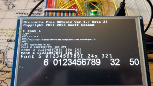
EDIT. Is it intentional that none of the SPI, I2C and ONEWIRE commands are mentioned in the command list of the User Manual, only in the appendix? The serial commands get a mention in the command list with a note to see the appendix. |
||||
| Greg Fordyce Senior Member Joined: 16/09/2011 Location: United KingdomPosts: 153 |
How about splitting the manuals in a different way. You could have a User Manual (including advanced features) and a Command and Function Reference Manual. This manual would include pages 42-70 of the User Manual and pages 31-42 of the Advanced Features manual. That gives a reference manual of around 39 pages, but as I mentioned in my previous post the SPI, I2C and ONEWIRE commands are missing so there are a few more pages to add. I think this would help when looking up a command or function, instead of having to flip back and forth in one manual you can open the other one for details without losing your place in the first one. Any thoughts on this? Greg EDIT: Regarding font numbers I just saw from Geoff's first post that the font numbering is supposed to be as shown in the manual so I guess that it will be changed in the next update to 4.7. |
||||
kiiid Guru Joined: 11/05/2013 Location: United KingdomPosts: 671 |
I vote in support of this concept. The separation should be on the basis of software/hardware reference, hence one document should be dedicated on the commands/functions only (this should be a really extensive one, with examples, and so on), while the other should be explaining the hardware - pinouts, external devices, etc... There was someone a while ago (sorry, can't remember the name right now), who wrote a very good book about the first maximite back then. Maybe he could find the time and exercise his book writing skills to make a new one? ;) http://rittle.org -------------- |
||||
| factus10 Regular Member Joined: 30/12/2014 Location: United StatesPosts: 45 |
Geoff, If you're interested, I'd love to help out with the manual. I have some experience with that sort of thing (a little DTP, helpdesk, etc). David |
||||
| MMAndy Regular Member Joined: 16/07/2015 Location: United StatesPosts: 91 |
Everything was running until I ran some demo controls.bas software. The touch did work previously and it was calibrated but then I get this constant Tera Term scrolling Error: Touch not calibrated. I cannot break out of this error loop to give it a GUI calibrate command. Also, I re-loaded the firmware twice and it still gives this looping error. Any thoughts appreciated! (MM+ 4.7B23 7" TFT)  |
||||
TassyJim Guru Joined: 07/08/2011 Location: AustraliaPosts: 6271 |
The continual error "Touch not calibrated" means that your touch interrupt is being triggered. It happened to me when I accidentally set the touch interrupt to the same pin as the SDcard present pin. The explore64 uses pin 14. If that is the case, try removing the SDcard so the card present goes open circuit. I might have that the wrong way around so try both inserted and removed. If you have used a different pin, test to see if it is held low and, hopefully, pull it high. The other fix is to reflash the firmware and check your pins before enabling touch. Jim VK7JH MMedit |
||||
| MMAndy Regular Member Joined: 16/07/2015 Location: United StatesPosts: 91 |
Thanks Jim ... We re-loaded the firmware twice. We are using 21, 18, 48 for the touch Our DC-DC power supply, for the TFT electronics, was running a tad over 3.3 VDC and we adjusted this supply down and this seemed to fix the problem?  |
||||
disco4now Guru Joined: 18/12/2014 Location: AustraliaPosts: 1001 |
uM2 with ILI9341 freezes and needs a power reset with CPU 10 I am finding that the CPU speed can't be set below 20MHz when using MM2 and the ILI9341. The code below runs the LCD demo and each time screen is touched steps CPU speed down. It freezes and needs a power refresh when 10MHz is reached. Can anyone verify this issue with their setup. OPTION EXPLICIT ? "CPU 48 ": CPU 48 ? "OK" ? CPUSpeed(0) 'poke word &HBF805830,1 CLS CONST DBlue = RGB(0, 0, 128) ' A dark blue colour COLOUR RGB(GREEN), RGB(BLACK) FONT 1, 1 BOX 0, 0, MM.HRes-1, MM.VRes/2, 3, RGB(RED), DBlue DO WHILE TOUCH(X) = -1 TEXT MM.HRes/2, MM.VRes/4, TIME$, CM, 2, 2, RGB(CYAN), DBlue TEXT MM.HRes/2, MM.VRes*3/4, DATE$, CM LOOP ? "CPU 20 ": CPU 20 ? "OK" ? CPUSpeed(0) 'poke word &HBF805830,1 CLS COLOUR RGB(GREEN), RGB(BLACK) FONT 1, 1 BOX 0, 0, MM.HRes-1, MM.VRes/2, 3, RGB(RED), DBlue DO WHILE TOUCH(X) = -1 TEXT MM.HRes/2, MM.VRes/4, TIME$, CM, 2, 2, RGB(CYAN), DBlue TEXT MM.HRes/2, MM.VRes*3/4, DATE$, CM LOOP ? "CPU 10 ": CPU 10 ? "OK" ? CPUSpeed(0) 'poke word &HBF805830,1 CLS COLOUR RGB(GREEN), RGB(BLACK) FONT 1, 1 BOX 0, 0, MM.HRes-1, MM.VRes/2, 3, RGB(RED), DBlue DO WHILE TOUCH(X) = -1 TEXT MM.HRes/2, MM.VRes/4, TIME$, CM, 2, 2, RGB(CYAN), DBlue TEXT MM.HRes/2, MM.VRes*3/4, DATE$, CM LOOP ? "DONE" END CFunction CPUSpeed 00000000 3c02bf81 8c45f000 8c43f000 3c02003d 24420900 7ca51400 70a23002 3c040393 34848700 7c6316c0 00c41021 00621007 3c03029f 24636300 10430005 00402021 00002821 00801021 03e00008 00a01821 3c0402dc 34846c00 00002821 00801021 03e00008 00a01821 END CFUNCTION GUI TEST DISPLAY will fail below 20MHz GUI TEST TOUCH will fail below 20MHz Thanks Gerry Latest F4 Latest H7 FotS |
||||
| TassyJim Guru Joined: 07/08/2011 Location: AustraliaPosts: 6271 |
I can confirm that my MX170 running 4.7 beta23 and a ILI9341 freezes during 'gui test touch' with a CPU 10 setting. I think any GUI command will fail with CPU 10. Jim VK7JH MMedit |
||||
| disco4now Guru Joined: 18/12/2014 Location: AustraliaPosts: 1001 |
The ILI9341 works at 10MHz with Peter's CFunction drivers for the ILI9341. I did slow the SPI command as below when initializing the ILI9341 in my Voltage Monitoring thingy. SPI should be maximum 1/4 clock I think. 'spi open 12000000,3,8 '48MHz Clock spi open 2500000,3,8 '10MHz Clock I slow the CPU to 10MHz to conserve power and speed up the 48MHz when you are interacting with it. For now I will only come down the 20MHz. I think it is something that could be made to work, perhaps the SPI speed remains set too high when the CPU is at 10MHz. The documentation seems to say SPI is adjusted if CPU speed changes, might just be overlooked for the LCD communication stuff on a change of CPU speed. Regards Gerry Latest F4 Latest H7 FotS |
||||
| The Back Shed's forum code is written, and hosted, in Australia. | © JAQ Software 2025 |
