
|
|
Forum Index : Microcontroller and PC projects : E 64 Bridge
| Page 1 of 2 |
|||||
| Author | Message | ||||
| MMAndy Regular Member Joined: 16/07/2015 Location: United StatesPosts: 91 |
E 64 Bridge Today, I created a beta "E 64 Bridge" PCB that connects the MicroMite+ Explore64 stamp module via ribbon cable to a 7" SSD1963 TFT display and to a PS2 mini keyboard. It has a buzzer driver Darlington, 5V back feed jumper/protection, headers for prototyping and a precision RTC with battery backup. All the electronics will be housed in a blow molded case for easy transport and operation. Due to long delays for parts purchased "off shore" this design and construction is ongoing ... Pic ... 2015-07-22_022802_E_64_Bridge_R1.pdf |
||||
| WhiteWizzard Guru Joined: 05/04/2013 Location: United KingdomPosts: 2991 |
Please explain more! |
||||
| MMAndy Regular Member Joined: 16/07/2015 Location: United StatesPosts: 91 |
Right now, on the present MM+ Explore64, there is no back feeding protection diode (& thermal fuse) in case a user powers both the MM+ E64 with USB power and also provides external 5V power at the same time. This would cause tying both 5V power supplies together which is not good. This simple "5V back feed jumper (5V VIN)" prevents this occurrence. Note: This jumper is used for testing. |
||||
bigmik Guru Joined: 20/06/2011 Location: AustraliaPosts: 2981 |
Hi Mmandy, I think you need to rotate your PS2 connector 90degrees clockwise otherwise the mounting screw top left corner will/might foul with plugging in the keyboard As it is the keyboard enters from the left hand side... Mick Mick's uMite Stuff can be found >>> HERE (Kindly hosted by Dontronics) <<< |
||||
| MMAndy Regular Member Joined: 16/07/2015 Location: United StatesPosts: 91 |
@bigmik If you can visualize this ... The display is on the left and the TFT 40 pin ribbon IDC connector is on the right mating with the E 64 bridge ribbon connector on the right. Since the E 64 bridge board is only 3.8" (96.52mm) x 2.5 (63.5mm)" then I want the P2S jack pointing up due to the abnormal length of the USB to PS2 adapter. I am planning to just use a flat head (countersunk) 4-40 screw in that mounting hole. The power jack should be pointing down in the base of the blow molded case. Note: Somewhere I read that Geoff will make is possible to use a USB keyboard instead of the PS2 keyboard? The "off the shelf" precision RTC takes up the most room, in board real estate, but it can be purchased for a very low "offshore" price. Note: The blow molded case is only 10.25" x 6.5" x 2.625" (26.035cm x 16.51cm x 6.6675cm) I am hoping to store the mini keyboard and power supplies (battery packs and AC mains) in the bottom of the case and use the inside lid for the display. Also, I am using Velcro and a thin piece of painted Masonite for mounting the electronics on the inside lid. My design goal is to have a compact, portable MicroMite+ AC/DC powered, low cost laptop. 
and the end result of having a computer "off the grid" and "off the network" with a self contained Basic development system with editor and SD memory storage. No IDE or PC required. Sorry NSA. 
|
||||
| bigmik Guru Joined: 20/06/2011 Location: AustraliaPosts: 2981 |
Hi MM, OK I follow: Of course you could do away with the PS2 socket and add a USB socket ... OK, it will be effectively only working as a PS2 keyboard mode and not USB mode but the thought there is why design in an adapter that is relatively large when you can just plug in a USB (PS2 compatible type of course) keyboard... Anyway I follow your thought process now. Regards, Mick Mick's uMite Stuff can be found >>> HERE (Kindly hosted by Dontronics) <<< |
||||
Grogster Admin Group Joined: 31/12/2012 Location: New ZealandPosts: 9975 |
[Quote=MMAndy]Right now, on the present MM+ Explore64, there is no back feeding protection diode (& thermal fuse) in case a user powers both the MM+ E64 with USB power and also provides external 5V power at the same time. Explore64 board does have a PTC, which is a polyfuse. It does not have the reverse-blocking diode, but version 1C will. Smoke makes things work. When the smoke gets out, it stops! |
||||
TassyJim Guru Joined: 07/08/2011 Location: AustraliaPosts: 6537 |
It should be easy to add the diode to the current boards. 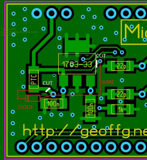
Still waiting on the postman for mine to try the mod on... I had a big piece cut out of my wrist this week so I couldn't hold a soldering iron yet anyway. Jim VK7JH MMedit |
||||
| Grogster Admin Group Joined: 31/12/2012 Location: New ZealandPosts: 9975 |
Yeah, I'm a bit "Annoyed" that I forgot that bloody diode. 
Oh well - you can only do your best. 1C will add this diode as standard. Smoke makes things work. When the smoke gets out, it stops! |
||||
| MicroBlocks Guru Joined: 12/05/2012 Location: ThailandPosts: 2209 |
I am not really a fan of the diode. It drops the voltage and that can be detrimental for things that need it. I prefer to have a 3 pin header and a jumper (or a mini switch). Microblocks. Build with logic. |
||||
| MicroBlocks Guru Joined: 12/05/2012 Location: ThailandPosts: 2209 |
To be future proof you couod add a few solder bridges that allow that usb connector te be connected to the ps/2 pins and later to the usb pins. Once a usb keyboard is supported you only need to change the solder bridges. Microblocks. Build with logic. |
||||
| MMAndy Regular Member Joined: 16/07/2015 Location: United StatesPosts: 91 |
To be future proof you could add a few solder bridges that allow the usb connector to be connected to the ps/2 pins and later to the USB pins.
Great idea, better yet, I will see if I can put a type A USB connector on board. So when the time comes either the PS2 mini DIN6 or the type A USB could be installed for the supported keyboard. Edit ... BigMik does have the best solution by just removing the PS2 connector and just use a USB A connector for the keyboard via PS2 emulation. This should save on the adapter cost and board real estate. As for the PCB wiring for the precision RTC ... I will make it so that either I2C (I2C1 or I2C2) is selectable by pad/jumpers and the default will be on I2C-2 channel 2. Note: Most, off the self RTC modules (DS3231/DS3232) already have the pull-ups built-in on their modules and the on-board 4.7k pull-ups are un-necessary. FYIO ... It's not evident, by the PCB pic, that I am using another "off shore" low cost, step-down DC-DC converter (5v to 3.3V) to power the TFT display. This will make it easy to power the complete system with only a +5v supply. They by having a 2.1 mm x 5.5 mm power jack to USB male adapter, all I need to do is to plug in a high current power pack for portable operation.
|
||||
BobD Guru Joined: 07/12/2011 Location: AustraliaPosts: 935 |
Andy, you may need to rethink that about the pull-ups. Here is a quote from the Pin Description diagram for SDA on a DS3231. The SCL is similar. [quote]Serial-Data Input/Output. This pin is the data input/output for the I2C serial interface. This open-drain pin requires an external pullup resistor. [/quote] Bob |
||||
| MMAndy Regular Member Joined: 16/07/2015 Location: United StatesPosts: 91 |
It pays to shop around ... The choice of keyboard was important and we decided to use Adafruit's mini PS2 keyboard. The size is only 8.75" x 4.65" or 22.22 c m x 11.81 cm. Due to this vendor's high cost, we found the same one for 1/3 the cost. http://www.ebay.com/itm/Mini-78-Keys-USB-Notebook-Laptop-Computer-PC-Keyboard-Black-/140710433003?pt=LH_DefaultDomain_0& hash=item20c2fed0eb
|
||||
| MMAndy Regular Member Joined: 16/07/2015 Location: United StatesPosts: 91 |
@Bob So far, the DS3231 "off shore" modules we got has the pull-up already built into (on) the module. You can check this by measuring with a ohm meter from Vcc to SDA and SCL. (The required external resistor(s) are on these module not IC's) What I was saying is that the pull-ups we put on the E 64 bridge, for the DS3231 RTC are not necessary. |
||||
| MMAndy Regular Member Joined: 16/07/2015 Location: United StatesPosts: 91 |
We like to point out that this project is for our internal use only and we have no interest or intention in promoting this E 64 bridge for commercial use. So any user can use our design and engineering in any which way that suits his/her fancy. 
|
||||
| BobD Guru Joined: 07/12/2011 Location: AustraliaPosts: 935 |
Andy, too ealy in the morning here. I missed the word "modules". Bob |
||||
| MMAndy Regular Member Joined: 16/07/2015 Location: United StatesPosts: 91 |
Ok Bob
On another note ... We just received the mini keyboard and we hope that the chip on the keyboard will do not only USB but also PS2. |
||||
| MMAndy Regular Member Joined: 16/07/2015 Location: United StatesPosts: 91 |
My neighbor just took over the E 64 Bridge PCB design. Here is his new design. (I was fired for designing the wrong pitch width 0.6" versus 0.9") 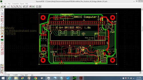
He also came up with some unique user applications for this BASIC portable computer. User Basic computer applications ... 1. Educational stand-alone BASIC computer. With a proper optional high current USB battery pack, the computer can run for hours without AC mains. 2. Data logging terminal. Having a precision on-board RTC with battery backup allows precise logging times. 3. Data communications terminal. 4. Home automation controller. 5. Secure data vault. With no PC and no network connection, data is somewhat secure. (Security can be greatly enhanced with additional hardware and software) 6. Data acquisition computer. 7. Game computer. 8. Hardware development computer. With plenty of GPIO still available, testing and developing new widgets can be easily accomplished. Exposed female headers on the "E 64 Bridge PCB" allows for easy bread boarding.
|
||||
| MMAndy Regular Member Joined: 16/07/2015 Location: United StatesPosts: 91 |
Updated features ... This project contains the MicroMite+ Explore64 stamp module (PIC32MX470 CPU) along with our custom designed peripheral "E 64 Bridge" PCB that allows a complete standalone modular BASIC computer with the following features: 1. User selectable mini PS2 or USB keyboard. Uses "offshore" USB or PS2 breakout modules. 2. Back feeding prevention (5V VIN jumper) when using both the 5V USB PC computer power and 5V external power. 3. LCD TFT display with touch ( SSD1963 5" or 7") with an easy to connect IDC 40 ribbon connector. 4. High efficiency DC-DC (5V-3.3V) step-down power converter module for LCD TFT display electronics. 5. Precision RTC (DS3231/DS3232) I2C module with battery backup. 6. "E 64 Bridge PCB" for all computer peripheral signal and power interconnects. Also, has a built-in Darlington sound buzzer. 7. All modular components (CPU, RTC, sounder, keyboard and power supply) can be easily user repaired or replaced. 8. Firmware for CPU could be upgraded by removing the MM+ Explore64 module and having a vendor upgrade it or by the PicKit 3 way. 9. Exposed development headers can used with external bread boarding. 10. Power status LEDs. Green for 5V power and amber for 3.3V power. As stated before all design files will be posted for user inspection. This project is for internal use only. |
||||
| Page 1 of 2 |
|||||
| The Back Shed's forum code is written, and hosted, in Australia. | © JAQ Software 2026 |
