
|
|
Forum Index : Microcontroller and PC projects : MM easy 232 interface in the manual...
| Author | Message | ||||
Grogster Admin Group Joined: 31/12/2012 Location: New ZealandPosts: 9975 |
Hi folks. 
With respect to this diagram from the MM manual: 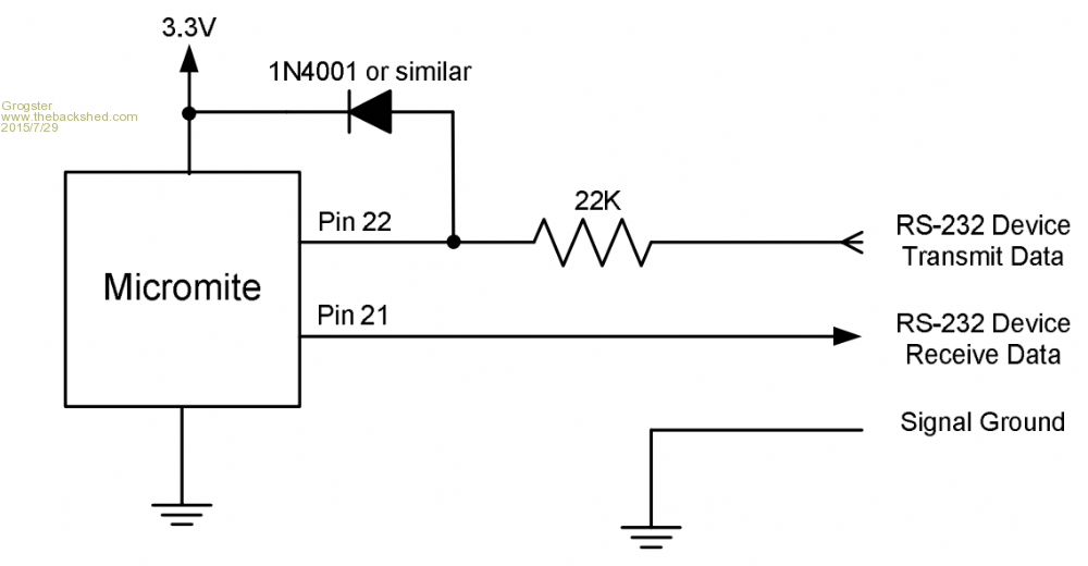
I don't follow the logic(pardon the pun) of this arrangement. Manual says that when RS232 from the PC or other 232 equipment swings to +12v, the diode will clip the voltage. HOW? With +12 from the 232 on the line, the diode will be forward biased, and both the MM input pin, and the 3v3 rail will see a 12v pulse. Surely that is not a good thing for a device not to exceed 3.6v absolute maximum. Obviously, there is something I am not understanding here, so I would love someone to help me follow this idea, cos I want to use it, but I don't want it to destroy the MM as soon as I put the 232 on the other side of the 22k resistor.... Smoke makes things work. When the smoke gets out, it stops! |
||||
| srnet Senior Member Joined: 08/08/2014 Location: United KingdomPosts: 164 |
Think about what the resistor will do. $50SAT is Silent but probably still working. For information on LoRa visit http://www.loratracker.uk/ |
||||
| Grogster Admin Group Joined: 31/12/2012 Location: New ZealandPosts: 9975 |
You mean along the lines of a potential divider at the point between the diode-side of the 22k and ground? Smoke makes things work. When the smoke gets out, it stops! |
||||
bigmik Guru Joined: 20/06/2011 Location: AustraliaPosts: 2981 |
Grogster, That works the same way that the protection diodes work for 5v.. You are not supplying a 12v power supply to the diode but a low current through 22k resistor so you will have 3.6 v on the anode side of the diode and (up to) 12v on the RS232 side of the resistor, the vcc supply to the pic will easily disperse any effect the low current would try to inject. This is the type of protection I used on the MuP-Security PCB .. Regards, Mick Mick's uMite Stuff can be found >>> HERE (Kindly hosted by Dontronics) <<< |
||||
| Grogster Admin Group Joined: 31/12/2012 Location: New ZealandPosts: 9975 |
...but when the 232 line goes to 12v, BECAUSE of the high-impdeance of the input pin, that pin would therefore see the 12v pulse, would it not? It looks like a dangerous idea, but then, I don't actually fully understand this concept yet!!!  Smoke makes things work. When the smoke gets out, it stops! |
||||
| bigmik Guru Joined: 20/06/2011 Location: AustraliaPosts: 2981 |
A problem with this circuit is the line will also swing NEGATIVE so a diode should also be placed between the Rx pin and GND (anode to GND and cathode to Rx) I believe there are these diode inbuilt on the pic pins but maybe not all pins have them Mik Mick's uMite Stuff can be found >>> HERE (Kindly hosted by Dontronics) <<< |
||||
| Grogster Admin Group Joined: 31/12/2012 Location: New ZealandPosts: 9975 |
It's quarter to one in the morning - obviously my brain is not working well. I will check in on this thread again in the morning. Night night.  Smoke makes things work. When the smoke gets out, it stops! |
||||
| bigmik Guru Joined: 20/06/2011 Location: AustraliaPosts: 2981 |
Grogs, 12v will not be seen at the pic because the diode will shunt it away to 3.3 which will not move so you will not see more than 3.6 v at the pic using.a schotky diode. Mik Dangerous?? Possibly if the diode fails or a solder joint fails but then the pic has protection diodes built in anyway... Mik Mick's uMite Stuff can be found >>> HERE (Kindly hosted by Dontronics) <<< |
||||
| srnet Senior Member Joined: 08/08/2014 Location: United KingdomPosts: 164 |
The resistor limits the current to a very low level. The output of the 3V3 regulator is very low impedance, I doubt it will shift at all due to the 360uA or so that comes down the resistor, it would not be much of a regulator if it did. As mentioned the PIC already has its own diodes built in. $50SAT is Silent but probably still working. For information on LoRa visit http://www.loratracker.uk/ |
||||
| Geoffg Guru Joined: 06/06/2011 Location: AustraliaPosts: 3362 |
On the PIC32 all normal (not 5V tolerant) pins have a diode to Vdd BUT the 5V tolerant inputs do not have the diode, so this is why I included the external diode (just to be safe). There is always a protective diode to Vss so this is why an external diode is not required for this function. Geoff Geoff Graham - http://geoffg.net |
||||
| Grogster Admin Group Joined: 31/12/2012 Location: New ZealandPosts: 9975 |
Thanks for all that, guys, I think I understand this now. Asking any technical question at 12:45AM when you are almost asleep at the keyboard, is probably not the best idea. I will therefore design this ciruit into the board I am designing for something, as it saves me having to have a 232 level shifter IC etc - PCB space is tight, so that will make my life easier if I don't have to squeeze the level shifter in there. Smoke makes things work. When the smoke gets out, it stops! |
||||
| Positron Newbie Joined: 09/08/2015 Location: ArgentinaPosts: 20 |
Hi Geoff, I think you should better recommend using a Schottky diode for clamping the voltage, because they have a 0.2 to 0.3 V dropout (instead of the 0.65 V of conventional diodes); this gives a 3.6 V (3.3 + 0.3) worst case maximun voltage on the PIC pin. I suggest changing the documentation to reflect this, replacing the 1N4001 with a 1N5819 or equivalent. Regards, JL. |
||||
| The Back Shed's forum code is written, and hosted, in Australia. | © JAQ Software 2026 |
