
|
|
Forum Index : Microcontroller and PC projects : Using MM for car ECU
| Author | Message | ||||
| MolsonB Regular Member Joined: 25/01/2015 Location: CanadaPosts: 48 |
I know I'm over my head right now, but slowly I'm sure this will work. I'm thinking of controlling an engine (Mazda Rotary RX8) using MM2/MM+. Now the thing to scare people, it's for a home built airplane. We currently don't have an aviation specific ECU and most end up staying carburetor or using a version of MegaSquirt. Now MegaSuirt uses an old 68HC908 (8mhz, 32k flash, 512 bytes ram), and only has a limited amount of inputs of sensors. With aviation, we want dual everything with a little extra. Plus we have a constant load which will make actual tuning easier (and simpler code). My idea is the MM will handle all the meat and potatoes (timing, sensor inputs, firing signals). From there it will Bluetooth (HC-05) all the data to tablet that will handle all the user needs (display, updates, timing changes and logging). Everything will be based on the timing of the Crank Sensor (36-2-2-2). If this can be done, the rest should slowly fall into place. The imagine below is for a Rotary Engine. I have the hardware done that converts the AC sine wave into a nice digital signal. The fastest the engine will spin is 10,000rpm (166.6Hz) 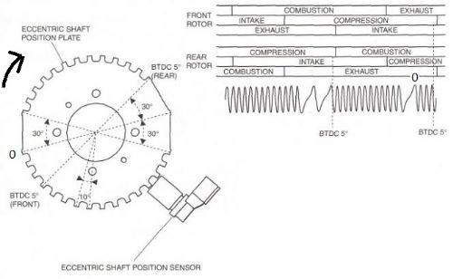
First the engine needs to get in sync with the crank sensor and turn over until it hits the starting point (the missing teeth 0). I'm thinking I have to find the period in between the teeth, to know when I'm on a single tooth vs missing teeth. To setup the teeth in an array, I'd use the degree's (10 degrees per tooth). tooth_deg[0] = 10;
tooth_deg[1] = 10 tooth_deg[2] = 10 tooth_deg[3] = 10 ..... tooth_deg[14] = 10 tooth_deg[15] = 30 tooth_deg[16] = 30 tooth_deg[17] = 10 tooth_deg[18] = 10 ..... tooth_deg[28] = 10 tooth_deg[29] = 30 Questions A. Based on all your experience, do you think this is plausible with MM? B. To get me started, how could I 'Count' pulse input but find out when I hit the missing teeth? Would I use 2 pins, one for an interrupt and one for period/counting? MkII 44pin - v5.0 ColorMax 2 - v4.5 |
||||
| JohnS Guru Joined: 18/11/2011 Location: United KingdomPosts: 4334 |
Do your local laws allow this? From the view point of the authorities: this is something that is potentially rather dangerous (to you/others)... What do you plan to do on such as a divide by zero or other error? John |
||||
| factus10 Regular Member Joined: 30/12/2014 Location: United StatesPosts: 45 |
Yes, it's a homebuilt plane. Allowed in the US and Canada. UK homebuilt options are considerably more restricted. MolsonB, get a copy of Don Lancaster's CMOS Cookbook (google for a PDF if you can't find physical copy). His Active Filter and Jung's Op-Amp Cookbook are good too. I'm suggesting these because what you're after is a missing pulse detector. Based on the drawing and signal info, the three flat spots on your position plate should trigger your missing pulse detector. You can send that signal to the MM and process accordingly. |
||||
| MolsonB Regular Member Joined: 25/01/2015 Location: CanadaPosts: 48 |
Yes it's home-built in Canada which has relaxed laws compared to UK. This is a 1-2 year project, with lots of bench testing and community involvement. Gotta start somewhere. The missing pulse detector with a 555 timer would work to find those missing teeth but I can't find a design that would handle the variable change in freq (different rpm of engine). I remember reading one of Don's books back in College, can't find the CMOS PDF yet. Software, I tried using 'TIMER' to capture the period of the previous signal, if the current signal period is longer, then I'm at a flat spot. SetPin 1, INTH, tach tach: tooth0_time = Timer tooth0_duty = tooth0_time - tooth1_time If tooth0_duty > (tooth1_duty + 1) Then Pin(2) = 1 Pin(2) = 0 End If tooth_num = tooth_num + 1 tooth1_duty = tooth0_duty tooth1_time = tooth0_time IReturn Attached 2 pics show it not reliable using TIMER, one rotation is correct and the other is off. I'm using another MM to generate the signal (so I can work at my desk and not in the garage). Correct rotation. 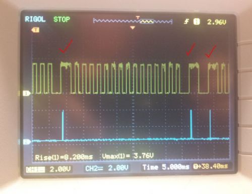
The next rotation is off. 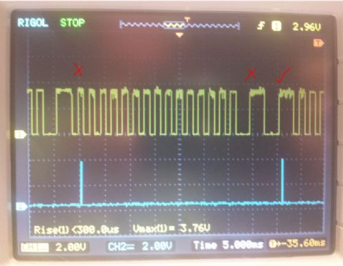
PULSIN might be what I'm looking for, but I don't have my PIK to update to latest firmware yet. It's almost like I need all 4 pins for the same signal. Interupt to handle the math, Freq to give me a snapshot at the RPM, Count to tell me which pin I'm at, and Period to help compare the previous tooth to flat spot. If I could find a missing pulse detector that would work with supplying a variable frequency, would be the cat'z azz. MkII 44pin - v5.0 ColorMax 2 - v4.5 |
||||
| MolsonB Regular Member Joined: 25/01/2015 Location: CanadaPosts: 48 |
After playing around with interrupts and timing, I don't think the MM will work. Unless I'm doing something completely wrong here, which is a good probability at this hour. Because some things just make no sense. The fastest I'll need to measure is 10,000rpm (166Hz). That is roughly 6ms revolutions of the crank wheel, and there is 30 teeth on the wheel. A period of 0.2ms. Settings up a PWM 5Khz frequency from another MM as a test, I created a very small program to see if I can read the pulses fast enough. Option DEFAULT NONE
Option AUTORUN ON Option EXPLICIT Dim INTEGER x DIM FLOAT tooth_time, tooth1_time, tooth_pul SetPin 1, INTH, Tach SetTick 1000, RPM, 4 loopything: ' If tooth_time > 0 Then ' tooth_pul = tooth_time - tooth1_time ' tooth1_time = tooth_time ' tooth_time = 0 ' End If goto loopything Tach: x = x + 1 ''tooth_time = Timer IReturn RPM: Print "Counts: " x " = " ((x/30) * 60) "rpm" x = 0 IReturn Results are pretty close. Counts: 4980 = 9960rpm I remove the double '' and add TIMER to the interrupt. Results drop. Counts: 4461 = 8922rpm I remove all the ' and results drop more. Counts: 3723 = 7446rpm And what baffles my mind even more, I comment out the TIMER and results are the worst yet. How does commenting out a task, drop performance? Counts: 2191 = 4382rpm I'm really not understanding the MM the best. People have it working with arduino boards and MegaSquirt uses an outdated 68HC908. Is there where people write their own C-Functions ? MkII 44pin - v5.0 ColorMax 2 - v4.5 |
||||
| matherp Guru Joined: 11/12/2012 Location: United KingdomPosts: 11493 |
SetPin 1, INTH, Tach is not a true interrupt. The pin is polled in the 1msec timer interrupt. The only true hardware interrupts are used for count and frequency. To do what you want on a MM you are going to have to do it in a CFunction and disable the clock interrupts while it is processing. Basically, you need compiled code to achieve the performance you want. If you want to do it in Basic you will have to try one of the various Basic compilers. I have used Swordfish very effectively for this sort of thing, there is a free version that will probably do all you need but it is not as easy to use as MM basic as you have to set up the port hardware etc. |
||||
| Greg Fordyce Senior Member Joined: 16/09/2011 Location: United KingdomPosts: 153 |
I would have to agree with matherp that this is probably a bit ambitious for a MM. But you could simplify the problem by using a single tooth sensor wheel. A single pulse gives you a reference for the crank position and the time between 2 pulses will allow you to work out when to fire the coils and injectors. |
||||
| MolsonB Regular Member Joined: 25/01/2015 Location: CanadaPosts: 48 |
That makes more sense with count/freq being a hardware interrupt. I'm assuming "PULSIN" is hardware too, whenever my PICKit comes in I can upgrade to 4.7 and play around with it. I thought I read, the software interrupt was polled after every line of code executed. So I figured it was faster then 1ms. I'm ok to dive in with CFunctions (thanks to the Peter's G8JCF/matherp and all their hard work there). Basically I'll want to monitor the CountIn hardware interrupt, disable any software interrupts, do any processing on the countIn counts, and return back to program. Did I understand you correct Peter? The MM2/MM+ will never support an external clock? Wondering if it makes sense to use an MM2 (28pin version), just for timing part and use another the MK2 (44pin) for all the A/D sensor conversions and other stuff that isn't timing critical. Once the wheel timing is established, the fastest an injector would pulse is every 3ms. (6ms for a complete revolution of the wheel, and 2 sparks per revolution of the wheel.) All of my coding experience is with user input to set the timing (VB, ASP, HTML, SQL). I haven't done anything based on a pulse signal before. This is all new to me. @Greg- I don't want to change the wheel just yet, would rather work with more 'stock' items that more people would have on their engine. MkII 44pin - v5.0 ColorMax 2 - v4.5 |
||||
| matherp Guru Joined: 11/12/2012 Location: United KingdomPosts: 11493 |
My error, I've checked the source and you are correct. The polling takes place after each line of Basic is executed. It is probably possible to do what you want in a Cfunction. You can disable the 1msec timer interrupt: long long stopclock(void){
mT4IntEnable(0); } and then use one of the other timers free-running without interrupts to do the timing: #define tmr1con *(volatile unsigned int *)0xbf800600 //timer 1 configuration register
#define tmr1 *(volatile unsigned int *)0xbf800610 //timer 1 counter tmr1con=0x8010; //turn on with scale 8 tmr1=0; //reset the timer //wait for whatever you are timing return tmr1; remembering to restart the clock after you have finished long long startclock(void){ mT4IntEnable(1); } In 4.7 pins can easily be monitored in Cfunctions using GetPinBit(pinnum) |
||||
| MolsonB Regular Member Joined: 25/01/2015 Location: CanadaPosts: 48 |
Is there access to the source code of MM? I'm trying to understand but find examples are easier to follow. I'd like to see how PULSIN is coded for example. Reading the CFunction PDF, I can't seem to understand how the register map follows. Taking for the samples in the PDF..... 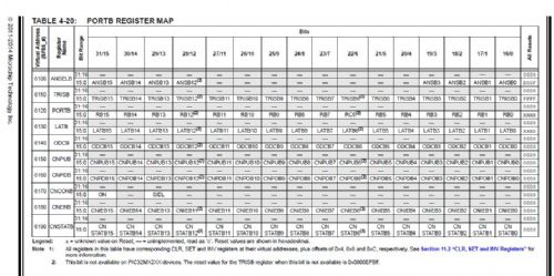
TRIS is the direction register if you want to make the pin Input(1) / Output(0). LATch is for writing, and PORT is for reading (for most situations) //RB1
#define pgdout *(volatile unsigned int *)0xbf886114 = (1 << 1) // Trisb<1>=0 - Output #define pgdin *(volatile unsigned int *)0xbf886118 = (1 << 1) // Trisb<1>=1 - Input #define pgd LATBbits.LATB1 #define readpgd() ((*(volatile unsigned int *)0xbf886120 >> 1) & 1) How does "0xbf886114" = B1? Wouldn't ...6114 be TRISB3 ? (1 << 1) gets me lost aswell. LATBbits.LATB1 must be defined somewhere to address writing to LATB1 to keep a cleaner code. I wonder what else is defined? I did a search in plib.h header files but couldn't find the actual definition. Same goes when reading the port, how does "0xbf886120 >> 1) & 1)" equal to 6121 (which I think is Port RB1) //RB2
#define clklo *(volatile unsigned int *)0xbf886134 = (1 << 2) // pin 6 Low #define clkhi *(volatile unsigned int *)0xbf886138 = (1 << 2) // pin 6 High To me, isn't the base of latchB2 0xbf886132?? I'm sure it has something to do with me not understanding the offsets and virtual addresses. *Edit: Is there a better forum I should be asking the C questions on? MkII 44pin - v5.0 ColorMax 2 - v4.5 |
||||
| JohnS Guru Joined: 18/11/2011 Location: United KingdomPosts: 4334 |
You have to ask Geoff (email/PM) for the source - details on his site. Port accesses abuse C using something like *(number with a cast to a pointer) The * (indirection) makes it go through to the actual port. Casting means telling the compiler how you want it treated (despite it being bad C). C compilers often let you do this on the understanding you suffer if you do something silly. Normally you want volatile in the cast, meaning you do not want the optimiser to remove any accesses. So the cast (volatile unsigned int *)0xbf886114 means to behave as if it is a pointer to an unsigned int (to whatever is at 0x...) and accesses should not be changed/reduced/increased from exactly what is written. Then *(volatile unsigned int *)0xbf886114 forces an access (read or write) to it. It's a bit ugly (but so would the ASM be) so is usually made to look better using #define You get the 0x.. (0x means hex) values from the chip datasheet. Expressions involving << and >> are shifts (left & right) by numbers of bits, so (1 << 1) means to shift 1 left by 1 place (making 2). It's done for (slightly more) readability. The value is worked out at compile-time by any modern C compiler so is exactly the same code as writing 2 (in this example). Readability is somewhat moot for low-level abuse of C, though!! John |
||||
| matherp Guru Joined: 11/12/2012 Location: United KingdomPosts: 11493 |
MolsonB every register has 4 addresses so, as an example, the base address of LATB (the output register) is 0xbf886130. If you write to this you set every bit on the port. However, there is an address that allows you just to set individual bits. This is at the base address + 4 There is a register that just allows you to clear individual bits at the base address + 8 Finally there is an address that allows you to toggle individual bits as the base address + 0xC so if I want to set bit 7 in the output of portB without changing anything else I just need to write 1<<7 to 0xbf886134 If I want to clear bit 5 I can write 1<<5 to 0xbf886138. Note that in this case I am writing a "1" to the address to clear the relevant bit. The 1<<n notation is just an easy way of converting the bit number to a mask to pick out a specific bit. e.g. 1<<0 = 1, 1<<7 = 128 This approach exists for most registers so to change an individual port bit to an output we can just write to that bit in the port's TRIS base address +8 To make it an input write to the the port's TRIS base address + 4 Hope this helps |
||||
| MolsonB Regular Member Joined: 25/01/2015 Location: CanadaPosts: 48 |
Excellent, that is starting to make sense. I've only programmed human readable code, never this deep in C with registers. I miss that feeling of learning something new and all of sudden the brain clouds clear up and 'I get it' feeling. Can I just clear up, reading the line in the legend is different then your offset Peter? base + 4 is clear (clears value back to 0) base + 8 is set (puts a 1 there) base + C is invert (if it's a 0, toggles to 1. if it's a 1, toggles to 0) MkII 44pin - v5.0 ColorMax 2 - v4.5 |
||||
| matherp Guru Joined: 11/12/2012 Location: United KingdomPosts: 11493 |
Absolutely correct, I got the set and clear the wrong way round  |
||||
| MolsonB Regular Member Joined: 25/01/2015 Location: CanadaPosts: 48 |
You don't know how nervous I was, asking that. I checked and re-checked and checked again to make sure. Then checked again.... Thanks a lot, clears that up with registers. I wonder if CFunctions almost needs it's own sub-forum in here? MkII 44pin - v5.0 ColorMax 2 - v4.5 |
||||
Bryan1 Guru Joined: 22/02/2006 Location: AustraliaPosts: 2092 |
Great Idea along with a sub forum for code snippets, libraries etc so members can easily find code without having to search for hours using the search function on the forum. |
||||
| Gizmo Admin Group Joined: 05/06/2004 Location: AustraliaPosts: 5182 |
Sorry Bryan the forum software wont let me add sub forums. I could add a section for "Code" to sit beside the existing Windmill, Solar, Electronics, Microcontrollers, etc sections, but then we have the problem of people posting code questions in the Microcontroller sections and visa versa. Glenn The best time to plant a tree was twenty years ago, the second best time is right now. JAQ |
||||
| MolsonB Regular Member Joined: 25/01/2015 Location: CanadaPosts: 48 |
With CFunctions, can we add our own interrupts or am I way off here? Can we 'hooks' into MM source code, say I want to expand the "count (CIN)" interrupt function? With the code below, I'm trying to setup an Input Capture to count the pulses. Once this basic footprint works, I can start actually writing C code. The code doesn't work below, either I didn't port the IC to external pin correctly, or I can't define interrupts like I did. I'm kind of wondering if I have to give up on MM, and just compile my own PIC. #define _SUPPRESS_PLIB_WARNING
#include <plib.h> #define IC2con *(volatile unsigned int *)0xbf802200 //Input capture 2 configuration register //#define IC2buf *(volatile unsigned int *)0xbf802210 //Input capture 2 //#define IC2r *(volatile unsigned int *)0xbf80fa2C // Input capture 2 peripheral pin select to input register map (tbl 4-22) #define RB9con *(volatile unsigned int *)0xbf886118 = (1 << 9) //TrisB<9> = Input (set 1) static volatile int count; long long main(void) { //Register values can only be changed if the Configuration bit, IOLOCK (CFGCON<13>), = 0. IC2R=0x0100; //Map IC2 to RPB9 (tbl 11-1) // configuring IC2 IC2CON=0x8306; //turn on rising edge 32bit timers2&3 // enable multi-vector interrupts - done in source code // enable capture interrupt mIC2ClearIntFlag(); mIC2IntEnable(1); return(count); } //IRQ 11, Vector 9, Persistent interrupt void __ISR( _INPUT_CAPTURE_2_VECTOR, ipl2) IC2_Handler(void) { // unsigned char test = IFS0bits.IC2IF; count++; // long long temp = IC2BUF; //"To clear an interrupt source, read the buffer result (ICxBUF) register...." mIC2ClearIntFlag(); } MkII 44pin - v5.0 ColorMax 2 - v4.5 |
||||
| matherp Guru Joined: 11/12/2012 Location: United KingdomPosts: 11493 |
Unfortunately I don't think this can work, when you compile a Cfunction the compiler switches we use (-fPIC -mno-abicalls) attempt to make the code position independent because at compile time we don't know where in memory it will reside (Microchip code isn't truly position independent and this is why there are limitations on what we can do with CFunctions). This means that the NVIC can't know where your interrupt routine is. The only way round this is to poll the inputs in the CFunction which is called every so often to establish the current engine operating characteristics. Then go away and process before polling again. What you can do is add the CFunction that does the polling, assuming it is reasonably short, into the 1msec timer interrupt. Look up PeterC's docs on how to do this - not something I have tried. UPDATE I've been thinking about this some more and if I were going to code this here is what I would do: Get the source for the MM firmware. This is freely available from Geoff for your own use - it may be worth waiting for the 4.7 source to be finalised and available for your final version but 4.6b is available now and you could make a start on this. The source is exquisitely written and easy to follow. In the external.c module are the true hardware interrupt routines that handle count and frequency input. I would then pick one or more of these and modify them to meet your requirement. They currently maintain static variables that are then available to you when you use "x=pin(y)" This way you can do much of the simpler programming in Basic but get the speed you need for the position sensing and spark firing. My calcs are that at 10,000rpm 1-degree of rotation take 16.66uSec so you can only handle this accurately in compiled interrupt driven code unless you code everything in C. Future updates to the MM firmware won't be an issue because your application is dedicated and you won't want to upgrade. Creating a personal version of the firmware will be much easier than trying to do this in CFunctions. Your posts above show you are getting into the hardware very quickly so I really don't think you would have any problem following this approach. Send me a PM if you want to discuss off-forum |
||||
| MolsonB Regular Member Joined: 25/01/2015 Location: CanadaPosts: 48 |
Sorry Peter, I didn't get an update email on your 'edit' post. The past few weeks I've been diving into C code. Been a few nights I get sucked in so bad, the sun starts to come up. Compiling my own code C-code will be the only way to handle the timing. For other projects in my mind, MM is still an easy and fast platform when timing is 1ms. Learning lots on Microchip.com right now. I'm still trying to wrap around my head how to handle the timing. If my math is correct 10,000rpm = 166hz = 6ms. There is 36teeth on the wheel, so each tooth will be read at 0.166ms (fastest case scenario). I'm still learning some basics but definitely want to pick your brain Peter on using Core vs Timers. MkII 44pin - v5.0 ColorMax 2 - v4.5 |
||||
| The Back Shed's forum code is written, and hosted, in Australia. | © JAQ Software 2026 |
