
|
|
Forum Index : Microcontroller and PC projects : MOSFET pain in the posterior...
| Author | Message | ||||
Grogster Admin Group Joined: 31/12/2012 Location: New ZealandPosts: 9975 |
I cannot make a simple MOSFET circuit work. The MOSFET stays on all the time, regardless of if the gate is high or low. Here is the circuit: 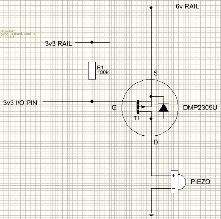
The 100k should keep the MOSFET off till the gate is pulled low by the PIC, but this is not happening. As soon as the circuit is powered, the piezo starts, and pulling the gate low or high does not stop it, even though the voltage on the gate with respect to ground is then zero volts or 3v3. I have used this circuit before with no problems at 3v3, but I would not have thought that changing the voltage on the S-D path would have any real effect, so can someone point out what the hell I am doing wrong? Most importantly, does a MOSFET's gate have to be driven at the same voltage level as the source supply voltage for it to work? I would not have thought so, but both MOSFET circuits are BOTH not working in exactly the same way. One has the piezo on it, and the other drives an LCD LED backlight(simple off/on), but the LCD backlight stays on forever too, no matter what you do with the gate. I tried removing the gate resistor, but that had no effect either. What's going on?  Smoke makes things work. When the smoke gets out, it stops! |
||||
| MMAndy Regular Member Joined: 16/07/2015 Location: United StatesPosts: 91 |
A good tutorial ... http://www.gammon.com.au/motors |
||||
| Grogster Admin Group Joined: 31/12/2012 Location: New ZealandPosts: 9975 |
Thanks - will read that. Smoke makes things work. When the smoke gets out, it stops! |
||||
| JohnL Senior Member Joined: 10/01/2014 Location: SeychellesPosts: 128 |
http://www.electronics-tutorials.ws/transistor/tran_7.html |
||||
| Grogster Admin Group Joined: 31/12/2012 Location: New ZealandPosts: 9975 |
Thanks John - will also read your link. 
It would seem that the gate must be the same voltage as the source voltage, for the MOSFET to fully turn off. Therefore, with that basic info in hand, I have a design issue, as the source is a higher voltage then the gate can ever be, so the the MOSFET stays on forever. That is how I am interpreting the reading thus far, and would also explain why previous high-side circuits using this MOSFET have worked - they had the source voltage at the same 3v3 as the gate voltage from the PIC. Smoke makes things work. When the smoke gets out, it stops! |
||||
| robert.rozee Guru Joined: 31/12/2012 Location: New ZealandPosts: 2527 |
the P-channel MOSFET starts to turn on when Vgs exceeds about a volt. in this case, you permanently have at least 2.7v (6 - 3.3) applied to the gate, therefore the MOSFET is permanently turned on. you can only use a P-channel MOSFET in this configuration IF you have your pullup running to the same place as the source ("6v RAIL") AND you use an open-collector output to control the gate. an open collector output from a maximite will not do, as the output will still not be able to rise above 3.9v (3.3 + 0.6) due to the protection diodes on the pin. you therefore need to use a second transistor, an NPN bipolar, to control the gate. the base of the NPN transistor should have a 47k or thereabouts resistor in series with it. when the maximite's output pin is low, the NPN transistor will be turned off (no base current), allowing the 100k resistor to pull the MPSFET's gate to the same voltage as the source. the MOSFET will therefore be turned off. when the maximite's output pin is high, current will flow through the 47k resistor into the NPN transistor's base, turning on the NPN transistor. this will cause a difference of about 6v to exist between gate and source of the MOSFET, thurning it on and causing the buzzer to sound. cheers, rob :-) |
||||
| matherp Guru Joined: 11/12/2012 Location: United KingdomPosts: 11493 |
Grogster Easiest solution I know is to use a npn transistor with the collector pulled to the 6v rail to switch the P-channel mosfet. Your circuit will probably work using a 5V tolerant pin in open collector mode with a pullup to 5.5V (maximum allowed). However, the 5V pins don't include PWM which may be an issue depending on the application. |
||||
| robert.rozee Guru Joined: 31/12/2012 Location: New ZealandPosts: 2527 |
example circuit, that has been posted on the forums before: 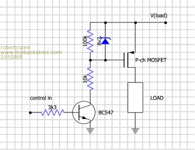
to match my above description, leave out zener, short out the 10k resistor, make the 3k3 resistor 47k. these changes are because you are only using a 6v supply and the buzzer will be drawing minimal current. cheers, rob :-) |
||||
| Grogster Admin Group Joined: 31/12/2012 Location: New ZealandPosts: 9975 |
@ Rob - excellent description - thanks.
Screen capture from the link MMAndy posted: 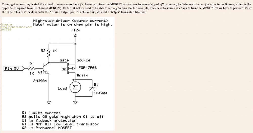
This tallies with Rob and matherp's posts too, so I will look into doing this. Smoke makes things work. When the smoke gets out, it stops! |
||||
| MMAndy Regular Member Joined: 16/07/2015 Location: United StatesPosts: 91 |
An alternative solution if you are only driving a piezo just use a Darlington that has a hfe of 1000 like TIP120. High = on and low = off.  |
||||
| robert.rozee Guru Joined: 31/12/2012 Location: New ZealandPosts: 2527 |
even a BC547 on it's own would probably be more than sufficient to drive a piezo placed in the collector (high size). for low current loads a bipolar transistor just is fine. cheers, rob :-) |
||||
| Grogster Admin Group Joined: 31/12/2012 Location: New ZealandPosts: 9975 |
@ MMAndy - It's funny you should say that, cos I am thinking along those lines now too. BC327 darlington perhaps? LCD LED backlight control has to be high-side, as it shares a common-ground with the actual LCD controller itself. Piezo could technically be a NPN transistor with the piezo in the collector circuit. EDIT: @ Rob - you beat me to it!(piezo in collector circuit) Smoke makes things work. When the smoke gets out, it stops! |
||||
| twofingers Guru Joined: 02/06/2014 Location: GermanyPosts: 1752 |
Hi Grogster, why not using a N-MOSFET for the piezo? Regards causality ≠ correlation ≠ coincidence |
||||
| Grogster Admin Group Joined: 31/12/2012 Location: New ZealandPosts: 9975 |
Yes, I could do that too. Smoke makes things work. When the smoke gets out, it stops! |
||||
| Grogster Admin Group Joined: 31/12/2012 Location: New ZealandPosts: 9975 |
UPDATE: I have fitted the NPN circuit to the MOSFET arrangement, and it is working great. Thanks for the pointers, folks. Smoke makes things work. When the smoke gets out, it stops! |
||||
| MMAndy Regular Member Joined: 16/07/2015 Location: United StatesPosts: 91 |
Another use for a mosfet ... For those wanting a reverse polarity protection this circuit will do it. It could be used on the MM+ Explore 64 stamp module on a breadboard to prevent reverse polarity and yet only have a few millivolts of drop! There are 3 pins, the GATE, SOURCE, and DRAIN, labeled G, S and D. you connect the * GATE to the + input voltage (pin 3 of the power jack in my diagram). * DRAIN to the - input voltage (pin 1 of the power jack in my diagram) * SOURCE to the GND of your circuit. http://www.instructables.com/id/Reverse-polarity-protection-for-your-circuit-with/ 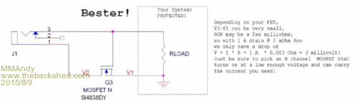
|
||||
| robert.rozee Guru Joined: 31/12/2012 Location: New ZealandPosts: 2527 |
you do need to be wary of the maximum Vgs of the MOSFET. for the Si4838DY shown, this appears to be 8 volts. so the above circuit, if using a 12v supply, will be operating outside of the MOSFET's absolute maximum ratings. to solve this problem, you can either pick a MOSFET with a suitably high Vgs(max), or add a zener diode between gate and source and add a suitable series resistor to the gate/zener. at the same time, i'd be inclined to consider using a MOSFET that is happy being placed in the +ve rail; modern P-channel MOSFETs have pretty good specs and will be quite adequate in most hobbyist applications. cheers, rob :-) |
||||
bigmik Guru Joined: 20/06/2011 Location: AustraliaPosts: 2981 |
Hi Grogster, All, This reminds me of all of the comments Re. the backlight circuit I did for the BackPack170 where people suggested I change to a Mosfet instead of the perfectly working BC337. Did anybody actually get a single mosfet (ie no second tranny etc) going as was suggested? I will be honest I didnt try as I had a circuit that worked and was (and still am) very happy with it. Regards, Mick Mick's uMite Stuff can be found >>> HERE (Kindly hosted by Dontronics) <<< |
||||
| The Back Shed's forum code is written, and hosted, in Australia. | © JAQ Software 2026 |
