
|
|
Forum Index : Microcontroller and PC projects : PIC16f1455 USB to Serial
| Page 1 of 3 |
|||||
| Author | Message | ||||
| HankR Senior Member Joined: 02/01/2015 Location: United StatesPosts: 209 |
New thread branching from "FTDI finally bit me". Okay, I missed it trying to find it before asking the question, but have found it now using the search term of "16F1455". For those interested in that recent thread from late July, the title is "PIC16F1455 USB Serial Bridge". The link you provided to the code: http://sky.geocities.jp/home_iwamoto/P16F145x/P16_L04.htm I was hoping that the serial side could be completely inverted for use with a PICAXE, but it looks like only the UART Tx pin on the 1455 can be inverted. That's still better than nothing. Hank |
||||
| Chris Roper Senior Member Joined: 19/05/2015 Location: South AfricaPosts: 280 |
There was a recent article in Nuts & Volts about inverting signals for PICAXE. I can't recall the issue off hand but will try and find it for you. He just used a couple of jelly bean transistors. Cheers Chris http://caroper.blogspot.com/ |
||||
| Chris Roper Senior Member Joined: 19/05/2015 Location: South AfricaPosts: 280 |
OK - Found it. It was July 2014, how time flies I thought it was more recent than that  here is the circuit, you need. There was not much supporting text but the circuit is self explanatory: here is the circuit, you need. There was not much supporting text but the circuit is self explanatory:
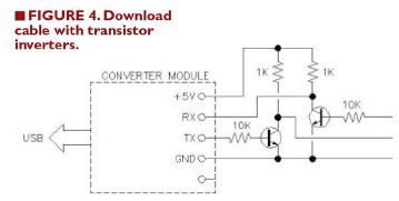
Cheers Chris http://caroper.blogspot.com/ |
||||
| Frank N. Furter Guru Joined: 28/05/2012 Location: GermanyPosts: 1101 |
Hi! Can anybody post the pre-compiled hex file??? Thanks! Frank |
||||
| Chris Roper Senior Member Joined: 19/05/2015 Location: South AfricaPosts: 280 |
Here you are Frank: 2015-08-20_102312_XBee_PIC16F1455.hex.zip Cheers, Chris http://caroper.blogspot.com/ |
||||
| Frank N. Furter Guru Joined: 28/05/2012 Location: GermanyPosts: 1101 |
SUPERB! 
Thank you very much!!! Frank |
||||
| Chris Roper Senior Member Joined: 19/05/2015 Location: South AfricaPosts: 280 |
For the sake of keeping everything in one place here is the schematic to aid in setting it all up. 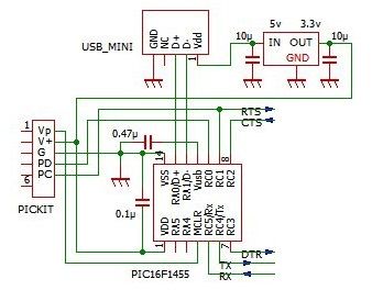
Cheers Chris http://caroper.blogspot.com/ |
||||
| SiNut Newbie Joined: 12/03/2015 Location: United StatesPosts: 12 |
I wish I had seen this thread before I purchased the MCP2221 USB-UART/I2C bridge from Microchip. The MCP2221 appears to be a 16F1455 device pre-programmed by Microchip to act as a USB converter. It has the essential Tx and Rx signals and works well with the Micromite-Mk2 (28 and 44 pin) and the ARMmite. It is missing the CTS, DTR and RTS signals. Microchip supports the device with detailed documentation, drivers and a configuration utility program. This utility can be used to reprogram several functions of the device and change its USB identifiers and descriptor strings. I purchased the MCP2221 for about a dollar (US) more than an unprogrammed 16F1455 from Mouser Electronics. I thought I would pass this information on for those who want a turnkey solution. Cheers, Singh |
||||
| MicroBlocks Guru Joined: 12/05/2012 Location: ThailandPosts: 2209 |
It is actually a PIC18F14K50. And it is programmed by Microchip who does not publish the software. It is impossible to make a copy as the chip is protected. You can write your own USB stack or find some open source code. There are a few around. You will miss out on the support though and that can be a deal breaker. Microblocks. Build with logic. |
||||
| JTR0701 Regular Member Joined: 10/07/2013 Location: AustraliaPosts: 71 |
No it's a 16F1455, you are thinking of the MCP2200 which is a 18F14K50, quite a different beast though. |
||||
| MicroBlocks Guru Joined: 12/05/2012 Location: ThailandPosts: 2209 |
Duh. I should read better. Only excuse is that it was late. 
On my search for some more source code that uses the USB in the F1455 i found this: https://github.com/todbot/blink1 It is from this project on kickstarter that got over $100.000. Not bad for a pic and 2 RGB leds.
Microblocks. Build with logic. |
||||
| isochronic Guru Joined: 21/01/2012 Location: AustraliaPosts: 689 |
Hmmm...there seem to be quite a few more new mcp2xxx variants.. adding SD, MMC, I2C, SPI and an A/D to the USB and UART..incorporating a 8051 - which I thought was an intel chip? What is microchip up to ? It suggests, a generic interface add-on is brewing. |
||||
| Chris Roper Senior Member Joined: 19/05/2015 Location: South AfricaPosts: 280 |
There are so many VHDL or Verilog Netlists of the 8051 floating around both IP and Public that they probably used one of those. Where did you see that list of new features? I must have a chat to my Local MicroChip Rep, he normally lets me know if any new devices are in the pipeline. I did get a message to say he has some samples that need collecting but I suspect they are just 18f1xKxx devices. Cheers Chris http://caroper.blogspot.com/ |
||||
| MicroBlocks Guru Joined: 12/05/2012 Location: ThailandPosts: 2209 |
http://www.microchip.com/wwwproducts/Devices.aspx?product=MCP2221 You need to scroll all the way to the bottom to see the list. Microblocks. Build with logic. |
||||
| MicroBlocks Guru Joined: 12/05/2012 Location: ThailandPosts: 2209 |
Chris, How did you wire up the 1455 and be able to choose between5v and 3v3? I know that supplying a voltage to VDD can be just a jumper. Did you also place a jumper to connect the Vusb3v3 to either a capacitor to ground or to VDD? I place some solder bridges, but would rather go without if possible. 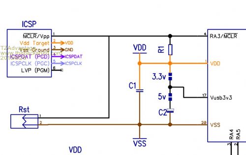
Microblocks. Build with logic. |
||||
| Chris Roper Senior Member Joined: 19/05/2015 Location: South AfricaPosts: 280 |
As above but no jumper on Vusb, I just tied it to ground via a Cap. The F series parts have an internal regulator, the LF parts tie it internally to Vdd so it should make no difference. I tested mine at both 5V and 3V3 without problems, but I have no idea what the Long-term result may be :) I even accidentally used an LF part and ran it at 5V for a couple of minuets and it worked, but I pulled power as soon as I noticed. Cheers Chris http://caroper.blogspot.com/ |
||||
| JTR0701 Regular Member Joined: 10/07/2013 Location: AustraliaPosts: 71 |
Just a back-up post to confirm what Chris already told you... As Chris said this is quite wrong. Do not ever put 5V on Vusb3V3. This is the USB voltage and it needs to be 3V3 always. Again Chris was right about the difference between the "L" parts and the "LF" parts. For "L" parts Vusb3V3 goes to a cap (has internal regulator) and for "LF" parts you supply 3V3 on this pin. USB is never switched btween 5V and 3V3, it is always @ 3V3, even in what otherwise may be a 2V system! It is the CPU, other peripherals and I/O that get switched between 3V3 and 5V via VDD. |
||||
| MicroBlocks Guru Joined: 12/05/2012 Location: ThailandPosts: 2209 |
In this case it is solely for the F part that has the internal voltage regulator. If the 5v solder bridge is closed and i provide 3.3v to vdd would that then still works. Basically what happens is that the internal voltage regulator gets 3.3v on its input. I wonder if the USB circuitry in the PIC will still work correctly in that case. In the current schematic it is either the 5v bridge or the 3.3v bridge that is closed. I would like to remove those bridges and connect Vusb3v3 with a cap to gnd directly. If 3.3v or 5v is supplied to the Vdd you then choose the output levels to prevent the use of level shifters. I specifically choose the F part for that. Having no solder bridges would make use of the module easier as someone could close both bridges and damage the PIC. Microblocks. Build with logic. |
||||
| Chris Roper Senior Member Joined: 19/05/2015 Location: South AfricaPosts: 280 |
Just tie it to ground Via a Cap. You can't feed 3v3 in on a 5V (F) part or you would be tying the internal regulator output to an external 3v3 supply. There is a drawing in the DataSheet with a note to say that connecting Vusb to 3V3 may work on an LF part but should NOT be done on an F part. I will try and find it. Cheers Chris EDIT: 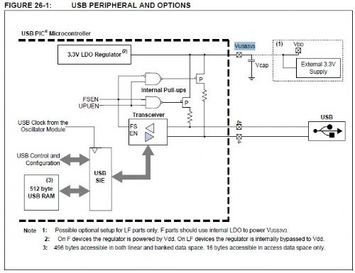
This caught me out at first as it is different to the PIC32MX250 Vbus connection. http://caroper.blogspot.com/ |
||||
| matherp Guru Joined: 11/12/2012 Location: United KingdomPosts: 11493 |
On an F part if you connect Vusb to 3V3 then the chip gets very hot and stops working  |
||||
| Page 1 of 3 |
|||||
| The Back Shed's forum code is written, and hosted, in Australia. | © JAQ Software 2026 |
