
|
|
Forum Index : Microcontroller and PC projects : PIC-KIT3 29 volts on MCLR. Why?
| Author | Message | ||||
crez Senior Member Joined: 24/10/2012 Location: AustraliaPosts: 153 |
device: OLIMEX PIC-KIT3 operating under IPE v2.25 device selected : PIC32MX470F512H under advance options: power device from tool. when I click connect I get two 100ms pulses 1.5 seconds apart of 29 volts on the MCLR line. Do I have some setting incorrectly set or do I have a faulty PIC-KIT? two dead mx470's so far...  |
||||
| MicroBlocks Guru Joined: 12/05/2012 Location: ThailandPosts: 2209 |
Goto settings->Advanced mode. Click Power and make sure the checkboxes under ICSP options are set right. There is a "High voltsge on MCLR" checkbox that might be on. I use IPE v3.05 (Maybe upgrade to that version, might be a bug in the previous ones as the mx470 are newer chips) Microblocks. Build with logic. |
||||
| robert.rozee Guru Joined: 31/12/2012 Location: New ZealandPosts: 2527 |
could be a good reason to not use a PICkit... 
it sounds like your PICkit 3 could be mistakenly identifying the PIC32 devices as some other family that requires/supports high-voltage programming. although, from what i recall, 29 volts is just a tad high for Vpp. before doing any further testing, i'd be soldering a 3v3 zener diode between MCLR and ground! either at the target, or on the cable coming out of your OLIMEX programmer. cheers, rob :-) |
||||
| crez Senior Member Joined: 24/10/2012 Location: AustraliaPosts: 153 |
Thanks TZ, under voltage settings it has "VPP: 3.3 N/A" under ICSP options I have ticked "power target from tool" the other two options ('low voltage program' and 'high voltage on MCLR') are greyed out and not ticked. I will see If i can find V3.05 |
||||
| crez Senior Member Joined: 24/10/2012 Location: AustraliaPosts: 153 |
Rob, what options are there besides PIC-KIT? |
||||
| matherp Guru Joined: 11/12/2012 Location: United KingdomPosts: 11493 |
When you selected PIC32MX470 did the system load the PIC32MX firmware to the programmer? The pickit3 needs differnt firmware depending on the target chip. It sounds like the programmer is operating in a mode for one of the early PICs that needed a high voltage on MCLR to initiate the programming sequence. However, even for these the voltage shouldn't exceed 13.5V maximum. Try using one of the dead chips but use external power for the PIC and then measure the voltages. You do have VCAP connected and some 0.1uF caps between VCC and GND near the processor? Difficult to diagnose remotely but it sounds like a faulty PicKit. The genuine Microchip programmers aren't very expensive and I have found them to be very reliable |
||||
| robert.rozee Guru Joined: 31/12/2012 Location: New ZealandPosts: 2527 |
pic32prog and an Arduino NANO. see this thread: http://www.thebackshed.com/forum/forum_posts.asp?TID=7762 cheers, rob :-) |
||||
| JTR0701 Regular Member Joined: 10/07/2013 Location: AustraliaPosts: 71 |
Sound to me the pickit 3 clone is very faulty, like one of the feedback resistors is open. I would not be looking to use it for any PIC without really troubleshooting this. A pickit should not ever produce that sort of Vpp output under any normal operating condition... |
||||
| crez Senior Member Joined: 24/10/2012 Location: AustraliaPosts: 153 |
The MCLR(yellow) and VDD(blue) pins of the programmer do this: 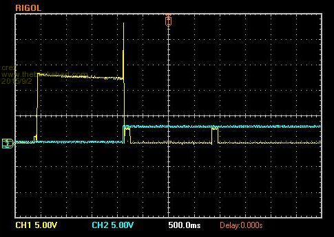
but the 13v peak only happens on the first CONNECT command after the USB is connected. Subsequent CONNECT commands behave as they should. These readings were taken with nothing connected. With a 4k7 load on the MCLR to GND, the peak is much shorter but still way over 3.3v As a precaution I have added 3.3v zeners between all the lines and GND. I also issued a connect command before connecting the target, and it seems the latest programming attempt has been successful. I also have a arduino mini on it's way so I can try Rob's method. Thanks all for your input. David |
||||
| The Back Shed's forum code is written, and hosted, in Australia. | © JAQ Software 2026 |
