
|
|
Forum Index : Microcontroller and PC projects : Intorducing MicroBlocks Prototyping
| Author | Message | ||||
| MicroBlocks Guru Joined: 12/05/2012 Location: ThailandPosts: 2209 |
Finally after almost one and a half year of testing and trying out different styles i have found the format i want to make MicroBlocks. As some of you know i have done a few MicroMite workshops at my MakerSpace here in Bangkok. I always used multiple sizes of breadboards, wires, the common modules etc to let people get acquainted with the MicroMite (Also CMM and MM). The biggest problem we ran into every time is that people connect wires to the wrong pins, just because counting all those little pins and holes is actually quit difficult. Especially when more and more wires are connected. Second problem is that the wires, even good quality ones, seem to not have very good contact. This is more a breadboard problem (see next problem). Wires are Male-Male for breadboard use and that is something that leads to making unintended connections with other pins just by touching them. Third problem is that breadboards, especially the cheaper ones, loose the clamping strength ones common modules are used that have header pins. Those are too thick, need a lot of force to put them into the breadboard and also a lot of force to get them out again. Then Big Mick came up with the MUP. This made things a lot easier. So much easier to get started, less mess with wired. We were happy with those. Still all the other modules where breadboard oriented. Getting rid of that breadboard was still impossible. This all led to a Prototyping system that i already have in my head for a long time. Biggest nuisance when prototyping is going to a product, or finalizing a one of project on its own pcb. So even with my MUP i struggled to make something i had into something permanent. To many wires still, but no way of getting it down in size. Well here is were the MicroBlocks Prototyping system comes in. First i had to determine a good size for a 'Block'. I want it to be as small as possible while still having a 0.1" grid. I first made a few simple modules that i use very often. USB power, USB-Serial, a Micromite etc.. Here are a few designs: USB Power 5v + 3.3v 500ma(23x10.5mm) 
USB-Serial and 5v + 3.3v 500ma (18x18mm) 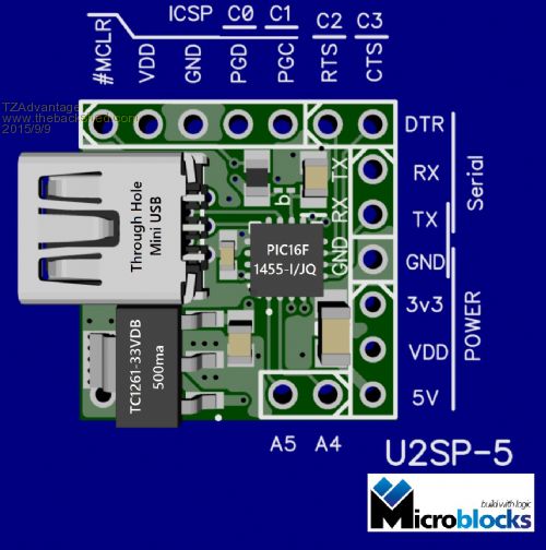
PIC32MX170 module with Supervisory Chip (23x18mm) 
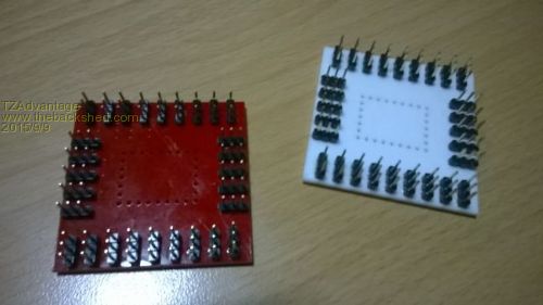
One of the advantages of the MicroBlocks Prototyping System is that it isn't limited by a dual in line design that is used for breadboards. Now pins can be on all sides. I cut a mockup on the lasercutter from acrylic to make sure all the sizes are good. Here are they (Excuus the quality) Here they are shown with header pins. 
Here one in its dead bug position. 
To prototype with these 'MicroBlocks' i have made a carrier board that makes working with such a small module much easier. They are 5x5cm and the pins are spaced more apart. Older guys will appreciate it. 
The 'Microblocks' can then be inserted in the center (female headers will be placed). 
This is then ready for prototyping. Once your prototype is working you would be able to use the EXACT same 'Microblocks' on a piece of prototyping pcb and copy the connections. One step further would be to download the 'Footprint' in your PCB editor and use them as part of your pcb. They can be soldered and even reflowed onto a PCB. The ultimate is to download not only a footprint but the 'Pads and Traces' of that module. (This is a service i would like to add later because this step is very difficult with current PCB programs). As a summary picture, top to bottom: First on the top left a USB breakout board, then a smallbreadboard with a 3.3v power supply and a PIC16F1455 DIP, then Big Mick's MUP. Right under it the 'Microblock Prototyping System" version of that consisting of two carrier boards with the modules USP5 and MX170. Under that the "microblocks' themselves. Those can be used to put on your own PCB. For size comparison, a PIC16F1455 and a 20 pin chip in DIP versions. 
Still under design is a mounting system for the carrier boards. Will be moveable so that when the one who must be obeyed says to clear the table it can be done in a few seconds. :) (This will also be a bi part of it as it is quit unique) This will go together with small boxes that will protect the bottom of the carrier boards. I would really like to hear some feedback. I tested it with a few people and they liked it. But having more eyes on it and hear some more opinions will be great. If you come this far in the post. Thank you for reading! Microblocks. Build with logic. |
||||
kiiid Guru Joined: 11/05/2013 Location: United KingdomPosts: 671 |
I can only say I wish you all the best luck with these. Many people (including myself) tried with different modular concepts over the past few years, some more successful, some less, but every next kit brings more options to the designers, and that is always a good thing. You have done a lot of work, and I hope you will see the fruits of it. Only one suggestion from me, if you allow: try to make them look a bit more consistent. Right now they are (kind of) every one for themselves. Try to stick to some compatibility, pins, shape/size, etc. Thus it will be easier to come up with new modules in future, and will make them more recognisable as well. http://rittle.org -------------- |
||||
| MicroBlocks Guru Joined: 12/05/2012 Location: ThailandPosts: 2209 |
My first versions where too complex. I tried to cram as much on a tiny module as possible. Only to find out in practice that they often missed something or had something that already used pins rendering the modules useless, etc etc. This time i just decided to make specific 'Blocks' that solve a specific problem or offer a specific function. There will be no bus, common pinout etc as this works against making more modules. There will be a 'style'. Inputs/power on the left. programming header on the top. Outputs on the right and bottom. Not a rule, just a preferred style. There are so many 'fixed' layouts, and i dislike most of them. Arduino shields, hats, grove, MicroBus/Click etc.. It is often not exactly what you need. To many unwanted 'extras', too big, not enough functionality, too much functionality, uses propriety busses/software, Lots of pins unused, not enough pins, etc, etc... Look here for an example of how much pins and in this case a whole bus connecter is used for a single button (ok and a led). A modular bus systems in my opinion misused for trivial stuff. What if you need 2 of them or 5. Completely impossible to use on their development boards. It is too rigid. A button does not belong on that system, there are buttons enough on the development board already, but once a 'Module Format' is chosen, everything has to stick with it. I feel that it can be done better, easier, cheaper. I am not picking on MikroE, they have lots of good stuff. It is just that i used them before and found it limiting. I think a'block' as small as possible and with a single function is best, but will have to see if i am right. At the other end there are 'Development boards'. They are often too expensive and have way to many switches, jumpers, etc. on it. MikroE has lots of them and i have used two of them. Probably 90% is not used. Waste of money and they get old quick. New MCU, new development board. With 'MicroBlocks' it is just another specific 'block'. No big costs, never buy more than you need. Easy to upgrade and expand. My feeling is that those are the most important aspects. And to give some more info. This is how it will look when you use a module in a Schematic. 
This example is another 'MicroBlocks' that is used for scanning a matrix and output it to a serialport (See the thread about a keyboard for the micromite). Or the other way around. Notice the internals. Not a 'Blackbox', but a block diagram of what is inside it. This helps in understanding the workings. Schematics of the 'block' itself will also be available, including a thorough description/reference or in the form of a datasheet. You can then make this part of a normal schematic, it also has a footprint and a 3D model. Currently i only do that for Diptrace, but Eagle and others are possible if needed. Lots more to do, like documentation, examples etc. One of the goals is to make a Microcontroller Learning/Experimenting kit. Microblocks. Build with logic. |
||||
| Zonker Guru Joined: 18/08/2012 Location: United StatesPosts: 772 |
Awesome TZ..! I like your blocks idea... Makes for easier prototyping...  |
||||
| MicroBlocks Guru Joined: 12/05/2012 Location: ThailandPosts: 2209 |
Thanks Zonker. More easy, more fun 
Microblocks. Build with logic. |
||||
bigmik Guru Joined: 20/06/2011 Location: AustraliaPosts: 2979 |
Hi TZ, Thumbs up from Me too. 
I have always liked the modular approach and SMALL.. Good luck with it all.. My only caveat is the QFN packages.. Hard to solder without an OVEN. Mick Mick's uMite Stuff can be found >>> HERE (Kindly hosted by Dontronics) <<< |
||||
| MicroBlocks Guru Joined: 12/05/2012 Location: ThailandPosts: 2209 |
Hi Mick, The QFN is the reason they are small, and being as small as possible is important. Plan is to have many 'Blocks' (about 20-30) on a single 10x10cm pcb and reflow them all at the same time. I have something in the works for that with a temperature controlled airflow preheating the pcbs from the bottom. Some tests show that it actually heats up pretty even and reflow happens. It might be all that is needed. And 10x10 is an easy size to work with to make a tiny 'oven' with very good temperature control. This would allow staying close to a reflow profile. For single tests the QFN's actually reflow pretty easy with a hot air station. Things that are left to solder are the through hole parts like the usb connector and the header pins. I plan to sell them with smd parts alrrady soldered and also complete with pins and connectors. The QFN's allows to make a PIC32MX170 'block' that is ready to go and still be relatively small with all pins broken out. Goal fom the mcu 'blocks' is to take out the repetitive things like having to add capacitors, resistors, crystal, and basic wiring like gnd and vcc connections. Doing that on a breaboard is not really easy, if not impossible. Get de tedious part out of prototyping, more reliable and more time for fun! Microblocks. Build with logic. |
||||
| MicroBlocks Guru Joined: 12/05/2012 Location: ThailandPosts: 2209 |
I might revisit this as someone recently posted about "tibbits" which comes very close to what i wanted. The "tibbits" enclosures are very affordable and give it a very professional look. I failed to get good enclosures for a reasonable price and this might be the solution to that problem. I have tested schematic designs from 28 pins MX170 up to the 100 pins (SSOP, TQFP but no more QFN's) ready to be routed on a specific PCB. If these tibbits are what they seem then conforming to their layout so that their enclosures can be used would be great. Microblocks. Build with logic. |
||||
| Tinine Guru Joined: 30/03/2016 Location: United KingdomPosts: 1646 |
Your MicroBlocks would go beyond prototyping use. I'll definitely be a customer :) Go for it (please)! |
||||
Grogster Admin Group Joined: 31/12/2012 Location: New ZealandPosts: 9932 |
Sounds like a plan. Has my vote. (for what it's worth) I will step away from designing anything as hinted in the other thread. I have too much to do anyway, so it's all yours MB!!!! Smoke makes things work. When the smoke gets out, it stops! |
||||
| MicroBlocks Guru Joined: 12/05/2012 Location: ThailandPosts: 2209 |
I'll start investigating the tibbits modules as it would be important to keep their pinouts compatible. I will also order some of their enclosures to get all the dimensions right. Any comments on which enclosures would be preferred to use are welcome. Microblocks. Build with logic. |
||||
| The Back Shed's forum code is written, and hosted, in Australia. | © JAQ Software 2026 |
