
|
|
Forum Index : Microcontroller and PC projects : Spinbox Object Display Format...
| Author | Message | ||||
| Zonker Guru Joined: 18/08/2012 Location: United StatesPosts: 772 |
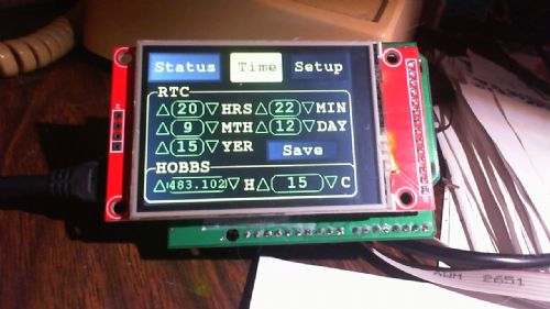
Evening Gents... I was working with the spin-box object and set it up to display 0 to 8000 with 0.1 steps.. After some play time, I discovered that after holding the UP arrow a bit, the box starts returning numbers with 3 digits past the decimal point instead of the 1 digit I set it up for... Is there any work around for this... The displayed number gets to long for the box and doesn't display right.... Thanks for any advice on this.. 
|
||||
| matherp Guru Joined: 11/12/2012 Location: United KingdomPosts: 11493 |
Probably a floating point rounding error in the value of 0.1 which accumulates after repeated "spins" include some code like (untested) i%=CINT(CTRVAL(#ref)*10.0) CTRVAL(#ref)=i% /10 to run after each "spin" or every n "spins" |
||||
| Zonker Guru Joined: 18/08/2012 Location: United StatesPosts: 772 |
Yep... (I'm a dumbass) 
I was using the "touch-up" INT for processing and was missing the "touch-down" INT's coming from the spin-box while holding down the "up-arrow" button... I put in your "steering" code if the INT found the object to be the spin-box on "touch-down"... Works like a champ..! 
Thanks Matherp..! |
||||
CircuitGizmos Guru Joined: 08/09/2011 Location: United StatesPosts: 1427 |
Love seeing what you are doing with the CGMICROBOARD2! Micromites and Maximites! - Beginning Maximite |
||||
| Zonker Guru Joined: 18/08/2012 Location: United StatesPosts: 772 |
Hey Thanks Robert..! Yea, your board works awesome for doing the prototyping work needed at this stage of development.. The cats love to fool around with the vector boards and all those wires going everywhere... They don't seem to bother with this just sitting in the corner by the phone...! Next, we need to add the rRs-485 IC and start talking to the display modules that sit in the cockpit.... Oh yea, I forgot to ask you what kind of regulators are on the board..? They seem to be from ST, but, I couldn't find any data on them... Whats the highest voltage I can apply to the input of the barrel jack..? So far it's just been running off the USB but will need to add the voltage monitoring part soon and was wondering how far to go up the scale.... Thanks Rob.. Great PCB.. |
||||
| CircuitGizmos Guru Joined: 08/09/2011 Location: United StatesPosts: 1427 |
ST LD1117S50TR Maximum of 15V input. http://www.st.com/web/en/resource/technical/document/datasheet/CD00000544.pdf Well thanks! Boards have been ordered for full production... Micromites and Maximites! - Beginning Maximite |
||||
| The Back Shed's forum code is written, and hosted, in Australia. | © JAQ Software 2026 |
