Notice. New forum software under development. It's going to miss a few functions and look a bit ugly for a while, but I'm working on it full time now as the old forum was too unstable. Couple days, all good. If you notice any issues, please contact me.
Grogster Admin Group Joined: 31/12/2012 Location: New ZealandPosts: 9975
Posted: 02:59am 14 Sep 2015
Copy link to clipboard
Print this post
Hi folks.
Most cooling fans have a tach output wire(usually yellow), which as I understand it, is connected to a hall-effect sensor on the motor, which outputs a pulse once per revolution of the motor, allowing systems to monitor the RPM of the cooling fan, and alert the user if the fan stops or gets too slow.
I am trying to understand how this works, but the info on the web seems vast and there seems to be lots of different diagrams on Google for exactly how this is done from motor to motor.
SO, my questions are:
1) IS this tach output a standard?
2) Is it a high or low-going pulse?
3) What is the output voltage if high-going - 5v?
I have hooked a motor up to my logic analyser, but am not getting any pulses on the yellow wire in either high or low with respect to ground.
If anyone has any additional information they can throw up on this thread, that would be very useful, as I want to use a fansink on my latest board, and was hoping to be able to monitor the motor tach, so that - just like with a computer - the system can alert the user if the fan stops or slows too much(gunked up).Smoke makes things work. When the smoke gets out, it stops!
matherp Guru Joined: 11/12/2012 Location: United KingdomPosts: 11493
Posted: 04:11am 14 Sep 2015
Copy link to clipboard
Print this post
The tacho signal is open-collector and needs a pull-up resistor
Greg Fordyce Senior Member Joined: 16/09/2011 Location: United KingdomPosts: 153
Posted: 04:13am 14 Sep 2015
Copy link to clipboard
Print this post
I just plugged a fan in to my oscilloscope and you need to use a pull up resistor on the yellow wire then you should get a square wave out of the yellow wire.
Grogster Admin Group Joined: 31/12/2012 Location: New ZealandPosts: 9975
Posted: 04:23am 14 Sep 2015
Copy link to clipboard
Print this post
Hey guys - thanks.
Therefore, the pulse will be low, if you need a pull-up.
I will hook up the fan with a pull-up tomorrow.(2:21AM now!)
If it is an open-collector output, even though I am driving the fan with 9v, I should be able to pull up to 5v or even 3v3, and it will still work(IE: tach line will pulse low), yes?
Never used these tach output wires before.
I did hook up an LED and resistor to this wire, but it did not blink at me, and I had tried it both ways. Oh well - will try pull-up and logic probe tomorrow and see if I get an output waveform then.
Night, night.Smoke makes things work. When the smoke gets out, it stops!
matherp Guru Joined: 11/12/2012 Location: United KingdomPosts: 11493
Posted: 04:28am 14 Sep 2015
Copy link to clipboard
Print this post
Yes.
On the fan I just looked at on my scope I get two pulses/revolution
Greg Fordyce Senior Member Joined: 16/09/2011 Location: United KingdomPosts: 153
Posted: 04:40am 14 Sep 2015
Copy link to clipboard
Print this post
My fan was one cycle per revolution, that is for half turn it was high and then low for the other half turn.
MicroBlocks Guru Joined: 12/05/2012 Location: ThailandPosts: 2209
Posted: 05:09am 14 Sep 2015
Copy link to clipboard
Print this post
A diode (maybe even a resistor) in series and a mcu IOport defined as input with pullup should work.
I might even put an ESD protection on those lines just to be sure.
Microblocks. Build with logic.
Grogster Admin Group Joined: 31/12/2012 Location: New ZealandPosts: 9975
Posted: 09:33pm 14 Sep 2015
Copy link to clipboard
Print this post
I am not getting ANY results, in any way, in any configuration, on any of the fansinks I have. These fansinks are all exactly the same.
So, I hooked up a Cooler Master PC cooling fan, and I do get a result from it:
This is what I would expect to get from the other fans, but don't.
I get no output at all. No response on rising or falling edge trigger, low or high pulse-width triggers.
I will pull one of these fans to bits, to see how it is wired up.
The image above, is with a 4k7 pull-up to 3v3 on the tach wire, and I just unplug the fan, and put one of the other fansinks I am trying to make work, in it's place, so exact same testing conditions, but no output at all from the fansinks I need to work - go figure.....
I can, naturally, just replace the fan with another known good 40mm fan, so it is not the end of the world. I will post back once I have gutted one of the problematic fans.Smoke makes things work. When the smoke gets out, it stops!
MicroBlocks Guru Joined: 12/05/2012 Location: ThailandPosts: 2209
Posted: 09:51pm 14 Sep 2015
Copy link to clipboard
Print this post
That would seem to indicate there is a wire but no sensor.
Maybe to save a few pennies?
Microblocks. Build with logic.
Grogster Admin Group Joined: 31/12/2012 Location: New ZealandPosts: 9975
Posted: 09:55pm 14 Sep 2015
Copy link to clipboard
Print this post
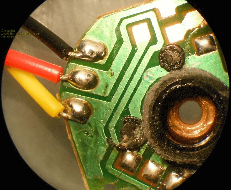
Well, this would explain quite a-lot........
There is a small chip inside the fan, but it is connected to the stator, and so I thus conclude that this chip is the driver for the fan, but there simply is no hall-effect sensor IC inside the fan at all - despite the yellow wire being there - good ole eBay......
I will just swap the fan for one that DOES have a tach wire. A working tach wire, that is.Smoke makes things work. When the smoke gets out, it stops!