
|
|
Forum Index : Microcontroller and PC projects : Fun with thermistors
| Author | Message | ||||
| matherp Guru Joined: 11/12/2012 Location: United KingdomPosts: 11604 |
Thermistors are a great way to measure temperature fast, quite accurately, and quite cheaply but need a bit of maths to get up and running. Lets take as an example the EPCOS B57560G104F THERMISTOR, 100K, 1%, NTC, RAD. The datasheet is available here Entering the table of temperatures vs resistance would be a complete pain but there is a mathematical mechanism available using the Steinhart-Hart equation temp (degrees C) = 1/(A + B*log(R) + C*((log(R))^3)) - 273.16 First we need to get the magic numbers for our thermistor A, B, and C. This is a one off for a particular model of thermistor and there is a great online calculator to do this for us. Select three temperature/resistance pairs from the datasheet covering the area of interest for your application and put them into the calculator and this will give the three Steinhart-Hart coefficients. Armed with these we can then do everything we want. This first function converts temperature to resistance: FUNCTION Temp_to_resistance(T as float,A as float,B as float,C as float) as float LoCAL x As float = (a - (1 / (T+273.16))) / c LoCAL y As FLOAT = b / c LoCAL R As FLOAT = 0 LoCAL a1 As FLOAT = (-x / 2) LoCAL a2 As FLOAT = (x ^ 2) / 4 LoCAL a3 As FLOAT = (y ^ 3) / 27 LoCAL b1 As FLOAT = (a2 + a3) ^ (1 / 2) LoCAL Alpha As FLOAT = (a1 + b1) ^ (1 / 3) LoCAL Beta As FLOAT = Abs(a1 - b1) ^ (1 / 3) R = (Alpha - Beta) Temp_to_resistance = exp(R) end function or we can convert resistance to temperature: function Resistance_to_temp(R as float,A as float,B as float,C as float) as float Resistance_to_temp = 1/(A + B*log(R) + C*((log(R))^3)) - 273.16 end function To use the thermistor in a circuit, the easiest way is to make it part of a potential divider. Connect one end of the thermistor to ground, connect the other end to a fixed resistor which in turn connects to VCC. For maximum sensitivity, choose the fixed resistor to be roughly equal to the thermistor resistance in the temperature region we are interested in. Connect the thermistor/fixed resistor junction to an ADC input on the microcontroller. It is worth doing this via a simple RC filter with a time constant appropriate to our measuring frequency. The thermistor itself should be chosen to have a resistance of around 5K in the temperature region of interest in order to meet the input impedance requirements of the ADC's input circuitry. Calculate the resistance of the thermistor using the function: Function Voltage_to_Resistance(VIN As FLOAT,VOUT as float,RTOP AS FLOAT) AS FLOAT Voltage_to_Resistance=RTOP/(VIN/VOUT-1) end function and if we know the expected resistance at a temperature we can calculate what the expected voltage should be: Function Resistance_to_voltage(VIN As FLOAT,RTOP as float,RBOTTOM AS FLOAT) AS FLOAT Resistance_to_voltage=RBOTTOM/(RTOP+RBOTTOM)*VIN end function Putting this all together with a simple test program we get: OPTION EXPLICIT OPTION DEFAULT NONE DIM volts as float dim float temp=100 dim float resistance=Temp_to_resistance(temp,0.6985229e-3,2.200879883e-4,0.7970586598e-7) print "Resistance at ",temp," = ",resistance PRINT "Check reverse conversion - original temp was ", Resistance_to_temp(resistance,0.6985229e-3,2.200879883e-4,0.7970586598e-7) volts= Resistance_to_voltage(3.3,4700,resistance)'get the target temp in volts Print "Voltage measured at ",temp," should be ",volts PRINT "Check reverse conversion - original resistance was ", Voltage_to_resistance(3.3,volts,4700) end ' function Resistance_to_temp(R as float,A as float,B as float,C as float) as float Resistance_to_temp = 1/(A + B*log(R) + C*((log(R))^3)) - 273.16 end function FUNCTION Temp_to_resistance(T as float,A as float,B as float,C as float) as float LoCAL x As float = (a - (1 / (T+273.16))) / c LoCAL y As FLOAT = b / c LoCAL R As FLOAT = 0 LoCAL a1 As FLOAT = (-x / 2) LoCAL a2 As FLOAT = (x ^ 2) / 4 LoCAL a3 As FLOAT = (y ^ 3) / 27 LoCAL b1 As FLOAT = (a2 + a3) ^ (1 / 2) LoCAL Alpha As FLOAT = (a1 + b1) ^ (1 / 3) LoCAL Beta As FLOAT = Abs(a1 - b1) ^ (1 / 3) R = (Alpha - Beta) Temp_to_resistance = exp(R) end function Function Resistance_to_voltage(VIN As FLOAT,RTOP as float,RBOTTOM AS FLOAT) AS FLOAT Resistance_to_voltage=RBOTTOM/(RTOP+RBOTTOM)*VIN end function Function Voltage_to_Resistance(VIN As FLOAT,VOUT as float,RTOP AS FLOAT) AS FLOAT Voltage_to_Resistance=RTOP/(VIN/VOUT-1) end function |
||||
| Zonker Guru Joined: 18/08/2012 Location: United StatesPosts: 772 |
Wow Pete...! I never thought you could just plug it into the MM input directly and get good results... This is awesome..! Thank you fine Sir.. You are an excellent teacher and offer up fine examples for everyone to play with..!  |
||||
| Geoffg Guru Joined: 06/06/2011 Location: AustraliaPosts: 3363 |
Yes, this is simply awesome and represents some great research. I am going to buy a few thermistor just to try this out. Somehow we need to collect this wisdom into something that will last. If you care to put it and your other wonderful tutorials into PDF's I would be more than happy to include them on my website and the Micromite downloads. Brilliant. Geoff P.S. I am amazed that you can do so much serious calculations while defining a series of LOCAL variables. Geoff Graham - http://geoffg.net |
||||
CircuitGizmos Guru Joined: 08/09/2011 Location: United StatesPosts: 1427 |
I have set up a PROJECTS section on my web site that allows for editing and pictures as well as file attachments. And then a comment area per project for people to contribute suggestions and bugs/typos. I think a lot of project information located in conjunction with other MM information would help a great deal. I'm growing it daily. Micromites and Maximites! - Beginning Maximite |
||||
crez Senior Member Joined: 24/10/2012 Location: AustraliaPosts: 153 |
After a bit of head scratching and brushing up on my maths, I have created a bit of code that does the job of the "great online calculator". This can be included in your main code. '---------------------------------- ' this code finds the values of a,b,c in the formula ' T=1/(a+b*log(r)+c*(log(r))^3) so that the three ' data points (r1,t1) (r2,t2) and (r3,t3) fit on the curve. 'once a,b and c are known, the temperature (K) can be 'calculated by entering the value of r 'into T=1/(a+b*log(r)+c*(log(r))^3) 'just change the values of r1,t1,r2,t2,r3 and t3 to suit your thermistor t0=273.15 ' 0 degrees Celcius in Kelvin r1=47000:t1=t0+25 'data point 1 resistance and temperature r2=20579:t2=t0+45 'data point 2 resistance and temperature r3=11751:t3=t0+60 'data point 3 resistance and temperature aa=(t2-t1)/t1/t2/log(r1/r2) bb=(t3-t2)/t2/t3/log(r2/r3) dd=((log(r1))^3-(log(r2))^3)/log(r1/r2) ee=((log(r2))^3-(log(r3))^3)/log(r2/r3) c=(aa-bb)/(dd-ee) b=bb-c*ee a=1/t2-b*log(r2)-c*(log(r2))^3 ? "a ";a,"b ";b,"c ";c 'now check that the curve fits the points 'resistance, T(from curve), T(input data point) ? r1, 1/(a+b*log(r1)+c*(log(r1))^3), t1 ? r2, 1/(a+b*log(r2)+c*(log(r2))^3), t2 ? r3, 1/(a+b*log(r3)+c*(log(r3))^3), t3 end '----------------------------------- David |
||||
| Phil23 Guru Joined: 27/03/2016 Location: AustraliaPosts: 1667 |
Found this thread & it's references very useful Peter. Thanks. I'm in the process of building a replacement controller board for a heat pump unit I'm converting to a Hot Tub heater. Original board is fried, but would also not work outside it's native environment, of the tank & associated sensors. 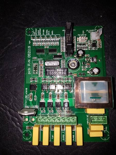
It accepted 5 thermistors from the heat exchange unit & another 4 from the water tank. 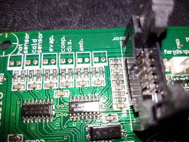
I just plan to use the 5 on the HP, primarily for protection of the unit. Have found a service sheet with resistance/temp test readings & also done my own readings from 0�C to 65�C. The devices appear to be Nominal 8k @ 25�C. Both sets give different Steinhart Coefficients & Beta values, but my own seem a better fit. What I'm looking for advice on is what is the best value series resistor to use with the Micromites analogue inputs. Trying 8.2k currently, but it appears the original circuit board used 10k's. The Thermistors monitor ambient, water in & out of heat exchanger, compressor & evaporator, with normal ranges of locations ranging from around 10� up to about 60�C. Compressor them is probably a crucial one, as on a couple of occasions I've had the compressor go into rotor lockup when water flow is lost & pressures rise. External temp of the unit climbing from mid 60's into the 90's. Not a good situation & would rather be catching it well before it happens. Any opinions on resistance values? Stay with nominal or a bit lower or higher. Thanks Phil Code I ended up with in case anyone could use it:- Dim Float TempNom=25 'Temp for nominal resistance (almost always 25 C) Dim Float ThermNom=8000 'Thermistor Resistance at Nominal Temperature (25 degrees C) Dim Float ThermSerRes=8200 'Value of the series resistor Dim Float StCo(4)=(0.1591512615e-3,3.643285819e-4,-1.094203586e-7,2984.90) 'Steinhart Co-efficients A,B,C & Beta Dim float ThermRes Dim Float ThermVolts Dim Float TempBeta Dim float TempStHart 'Pins used - Inputs Dim float PinTmp=22 '1-Wire DS18B20 Input Pin SetPin 4,AIN ThermVolts = Pin(4) ThermRes=ThermSerRes/(3.3/ThermVolts-1) TempBeta = 1/(1.0/StCo(4)*Log(ThermRes/ThermNom)+1/(TempNom+273.15))-273.15 TempStHart = 1/(StCo(1) + StCo(2)*Log(ThermRes) + StCo(3)*(Log(ThermRes))^3)-273.15 |
||||
redrok Senior Member Joined: 15/09/2014 Location: United StatesPosts: 209 |
While I dislike thermisters, here is a reference that is useful: Steinhart�Hart equation redrok |
||||
| crez Senior Member Joined: 24/10/2012 Location: AustraliaPosts: 153 |
Choose the same resistance as that of the thermistor at the middle of the range of the temperatures you are trying to measure. This maximises the worst-case temperature resolution. I have attached a graph from an excel spreadsheet that I made to help visualise the situation. e.g. if you want to measure from 20c to 40c, calculate your thermistor resistance at (20+40)/2 ie 30c. Use approximately this resistance to analog Vdd to bias the thermistor. David 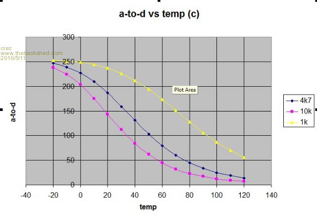
|
||||
| Phil23 Guru Joined: 27/03/2016 Location: AustraliaPosts: 1667 |
Thanks David, That's the answer I was looking for. As I mentioned, Temps will range from 0 to 65+ maybe, but eache thermistor has a different task. Ambient Sensor will be in the 20-30 range. Input & Output Sensor in the 30-40 range. Compressor, 60-90 range, intended to detect compressor over temp. Evaporator in the 0-Ambient range, with it's main purpose being avoiding frosting. Main ones I'd be interested in seeing accurate are ambient, In & Out Temps. Values I measured & the quoted values were:- 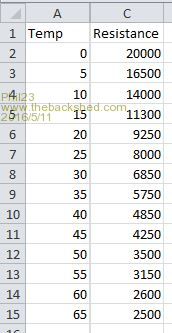
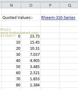
So I'm probably better off going with 8k or lower even, as opposed to the 10k the original control board used. Or I could mix values & deal with in in software, but could be a bit of a pain. Thanks Phil |
||||
| The Back Shed's forum code is written, and hosted, in Australia. | © JAQ Software 2026 |
