
|
|
Forum Index : Microcontroller and PC projects : uM2(+): AD9833 Function generator
| Page 1 of 2 |
|||||
| Author | Message | ||||
| matherp Guru Joined: 11/12/2012 Location: United KingdomPosts: 11142 |
The AD9833 is a DDS function generator programmable by a SPI interface. The version I bought , pictured below, includes a MCP41010 8-bit digital potentiometer and an opamp to boost and control the amplitude of the output. 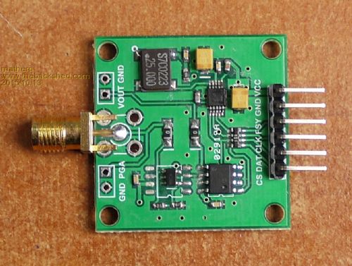
The attached Basic program shows how to control both the potentiometer and function generator to create Sine, Triangle, and Square waves of varying amplitude and frequency. It would be easy to combine this code with the GUI from this post to make a complete application. OPTION EXPLICIT OPTION DEFAULT NONE ' ' AD9833 Control Bits ' CONST B28%=&H2000 CONST HLB%=&H1000 CONST FSELECT%=&H800 CONST PSELECT%=&H400 CONST RESET%=&H100 CONST SLEEP1%=&H80 CONST SLEEP12%=&H40 CONST OPBITEN%=&H20 CONST DEV2%=8 CONST MODE%=2 ' ' Micromite pin allocation ' CONST CS%=24 ' pin for MCP41010 chip select (CS) pin on module CONST FSY%=23 ' pin for AD9833 chip select(FSY) pin on module ' ' Output modes ' CONST TRIANGLE%=1 CONST SINE%=0 CONST SQUARE%=-1 ' pin(CS%)=1 PIN(FSY%)=1 setpin CS%,dout setpin FSY%,dout spi open 1000000,2,16 'has to be mode 2 for AD9833, MCP41010 doesn't seem to mind ' updateamplitude(255) 'scale output 100% DO updatefrequency(20000,SQUARE%) '20KHz square wave pause 2000 updatefrequency(10000,TRIANGLE%) '10KHz triangle wave pause 2000 updatefrequency(40000,SINE%) '40KHz sine wave PAUSE 2000 LOOP end ' sub updateamplitude(i%) ' Sets the output of the MCP41010 digital potentiometer (0-255) local j%=&H1100 OR (i% AND 255) pin(CS%)=0 spi write 1,j% PIN(CS%)=1 end sub ' sub updatefrequency(fin%, wave%) 'Sets the frequency (Hz) and waveform of the AD9833 (Sine:wave%=0, Triangle:wave%=1, Square:wave%=-1) local oscillator%=25000000 'Crystal frequency local twoby28%=268435456 '2^28 local f%=(fin%*twoby28%)\oscillator% LOCAL c%=0 local f1%=(f% and &H3FFF) OR &H4000 local f2%=(f%>>14) OR &H4000 LOCAL p%=&B1100000000000000 if wave% =1 then c%=c% OR MODE% if WAVE%=-1 then c%=c% OR SLEEP12% OR OPBITEN% OR DEV2% pin(FSY%)=0 spi write 5,c% OR RESET% OR B28%,f1%,f2%,p%,c% ' print bin$(c% OR RESET% OR B28%,16)," ",bin$(f1%,16)," ",bin$(f2%,16)," ",bin$(p%,16)," ",bin$(c%,16) PIN(FSY%)=1 end sub |
||||
boss Senior Member Joined: 19/08/2011 Location: CanadaPosts: 268 |
Nice idea another choice is to use an optical encoder. I found this one (Grayhill with push button) on ebay for ~$10 new. 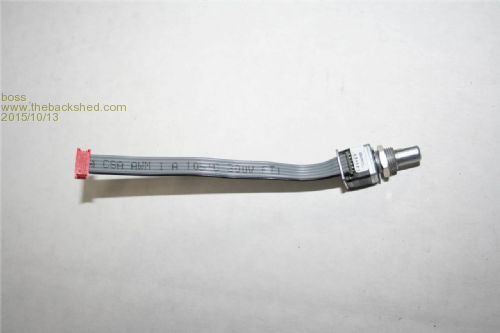
|
||||
disco4now Guru Joined: 18/12/2014 Location: AustraliaPosts: 1109 |
I ordered one of the AD9833 modules above sometime ago and started to write a GUI for it. I was removing the header pins to put it into a case when I made it not work by breaking some tracks. So I ordered another one and then also managed to repair the first one. So I updated the GUI to make a dual channel signal generator. It looks like this. 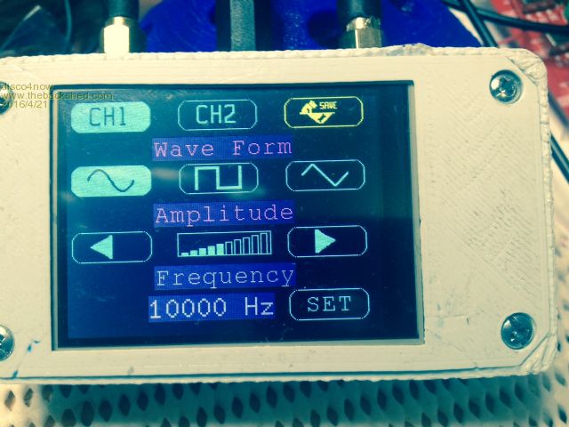
The code for an MM2 with a 320*240 screen is below. It uses all Peter's code, gets a few ideas from Parking Assist and Boat computer, and I used FontTweak to make the graphic fonts. Thanks,Peter,Geoff and Jim. I terminate the signal output in a 50ohm resistor as its supposed to be 50ohm output impedance. The software works without any hardware attached so it can be run to get a feel for the interface with just the MM2. 2016-04-21_131530_SignalGeneratorAD9833_v1.0.bas.zip Regards Gerry F4 H7FotSF4xGT |
||||
| hitsware Guru Joined: 23/11/2012 Location: United StatesPosts: 535 |
If one wants a really clean output signal, DDS is NOT the way to go. The residual digital garbage is always somewhat remaining. (filter as one may) A controller running an analog chip (ICL8038 or XR2206) (and the peripherals) will give much better results. Though perhaps not as handy . |
||||
| matherp Guru Joined: 11/12/2012 Location: United KingdomPosts: 11142 |
Gerry Excellent GUI and I really like the dual channel capability congrats 
I've used the XR2206 and IMHO it is not a good device. You need two pots to adjust the symmetry and distortion of the waveform (how do you do that without an expensive spectrum analyser? Also the XR2206 generates a sine wave by diode shaping of a triangle wave. There is a small glitch in the sinewave that is generated at the peak of the triangle wave, which is also the transition point of the square-wave output. To get rid of this you need a low-pass filter so no advantage over DDS |
||||
| hitsware Guru Joined: 23/11/2012 Location: United StatesPosts: 535 |
matherp , I happened to buy one of these after disappointment with DDS : http://www.sinometer.com/uploadImage/2012-09-27/2012092714544811255546.jpg It was after the purchase that I found it used 8038 with microprocessor. No glitch @ the peak (I've seen that myself) It must have some filtering, but the DDS units I've seen always have little steps left in the signal that annoy me. (But then I won't use a digital scope for the same reason) ... MegaRegards ..... hitsware |
||||
| robert.rozee Guru Joined: 31/12/2012 Location: New ZealandPosts: 2499 |
digital scopes are a very good example of a really useful tool for certain tasks, masquerading as a very different tool that is emulated poorly. over the years i've used several different DSOs (including $50,000 agilent models), and been highly disappointed with their inability to work like an analog scope. but this is the nature of the beast - DSOs are not a real-time display device, they are a high-speed data acquisition system who's output is best viewed after the event. an analog scope, on the other hand, does not acquire data, but merely displays an event as it happens, with the successful displaying being largely dependant upon the event being repetitive. there are many tasks that a DSO performs admirably, tasks that an analog scope could not handle. similarly, there are tasks that an analog scope can do most successfully, but at which a DSO struggles or fails completely. a modern 4-channel DSO with deep memory is magic for digital work, but no replacement for a relatively inexpensive (older) analog scope when you're doing RF work. much the same holds for digital synthesised signal generators. cheers, rob :-) |
||||
| hitsware Guru Joined: 23/11/2012 Location: United StatesPosts: 535 |
What the world needs is an analog flat panel display ! |
||||
| damos Regular Member Joined: 15/04/2016 Location: AustraliaPosts: 81 |
Funny, lots of people must be thinking the same thoughts. I bought a really cheap AD9833 module ($7) and added a 7-bit pot, a 50 ohm driver and an incremental encoder to set the frequency and output level. It works really well. Here is the source code.2016-04-24_045753_function.zip It uses the Micromite backpack and has touchscreen support. Features 0-12.5MHz with 0.1Hz increments Square, Triangle and Sine outputs Fine and Coarse Adjustment of frequency through encoder Numeric entry of frequency through keypad Sweep mode with 3 sweep speeds Remembers last 3 frequencies This will work with the other modules described here with a few small modifications to the code. If anyone want my circuit diagram, please ask. I used a PEC16-42 24-detent incremental encode available from Element14 for a couple of dollars. These things are cheaper than pots, and can then be re-used by the software. Also much better when you want to save favourite values. In terms of the DDS, the output is VERY clean, one of the best sine wave sources I have ever used. The XR2206s are awful and a really designed for RC setup rather than microcontrollers, and while a good Wein bridge is very clean, they can be very contankerous. |
||||
| boss Senior Member Joined: 19/08/2011 Location: CanadaPosts: 268 |
@damos Nice project indeed. Could you release schematics? Bo |
||||
| damos Regular Member Joined: 15/04/2016 Location: AustraliaPosts: 81 |
2016-04-25_075908_function_gen_circuit.zip Sorry about the hand drawn design. It doesn't have a huge output swing (600mV p-p), but it does drive 50ohms. I would add a gain stage if I was better at RF. I built this on prototyping board and it works very well. I'd be inclined to use the fully implemented board if buying from fresh. The code could be easily modified to suit. You could probably get away with a single 5V supply, although I haven't tested the LTC1010 with it. If you want to use the sweep, think about adding a couple of lines of code to output a pulse at the start of the sweep to trigger the DSO. The code implements a basic windowing API. I know the mm plus has this already, but there is no space left on the mm2, so I don't think it will be added. This allows you do create dialogs by defining the controls and providing a command code. This does all the drawing and touch detection, so you just need to add case statement entries for your event handler. I had a go at using gradients for buttons - the code is in my bas file. They look really good, and change the appearance to look professional, but are a bit slow to draw so they need to be implemented in C. |
||||
| boss Senior Member Joined: 19/08/2011 Location: CanadaPosts: 268 |
@damos Thank you very much. I'd like to have constant signal level in frequency range from 1000 Hz-12.5 Mhz, but no fully success yet. The signal generator is built on SnadPic (MM+ 100 pin) board so I have plenty of pins left for additional functionality . I tried to use some ultra-fast operational amplifiers, but nothing works fine. I'm surprised you are omit LP filter on DDS output. Did you check the output signal with oscilloscope? May be the LT buffer chip will work for me as well. 
Regards Bo Btw The chip is LT1010CN (not LTC1010 as is in diagram) |
||||
| damos Regular Member Joined: 15/04/2016 Location: AustraliaPosts: 81 |
The module I used is this one: http://www.ebay.com.au/itm/Programmable-Microprocessors-Sine-Square-Wave-DDS-Signal-Generator-AD9833-Module-/14162576949 3 It includes a 22pF capacitor on the output which I assume is adequate for a low pass filter. My design decisions on this project were: no surface mount, and the lowest cost components. Apart from the mm backpack, there are only $20 worth of components that aren't already in my component drawers. On my Rigol DS1052 DSO the output is very clean up to a few MHz. Above that it is quite useable, but not necessarily a clean sine wave. I expected that because I am using prototyping board rather than a proper ground plane, so lots of yucky things could be happening. I mainly wanted it for audio work so 1MHz is heaps, and this is much better than that. The signal level is quite constant across the range. I am sure a proper filter may improve performance above 1MHz. The LT buffer works very well and is effortless to use. I tried to use an old wideband CA3130 op amp (all I could get on a Saturday afternoon), but it oscillated like crazy on prototype board, while the LT is really well behaved. I did some reading online, and the CA3130 is seen as a really old piece of junk, so I thought I would leave the extra gain for another day. Most of my work only needs a few hundred kHz, and I can do that easily. This is replacing an old HP 200CD signal generator. It is a really nice design for 1960s, has a really clean output, and they did a lot to stop the output bouncing around. Unfortunately it is not stable on the low ranges and after numerous attempts to repair it is just too much trouble. As far as I am concerned, the Ad9833 kills it. |
||||
jman Guru Joined: 12/06/2011 Location: New ZealandPosts: 711 |
Hi I had just finished my dual AD9833 Function generator before I saw the article in SC. So I thought I would share it. My version uses Micks BackPack170 Micks BackPack170 I used the software posted by Disco4Now and added a rotary encoder and some code to use the encoder. The encoder has a built in switch so a quick press sets the multiplier from x1 to x10000 in 4 steps and longer press (+-2 seconds) updates the AD9833 with the new frequency. Pic of the completed unit below 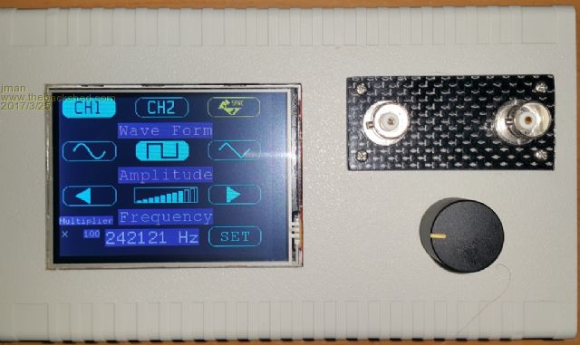 I will post the code if anybody is interested. Regards Jman |
||||
| nibbler Newbie Joined: 18/04/2013 Location: CanadaPosts: 11 |
@jman Hi I'm interested in the code for your dual AD9833 Function Generator. Could you also supply a link to the rotary encoder you used? Thanks. Alan |
||||
crez Senior Member Joined: 24/10/2012 Location: AustraliaPosts: 152 |
I am also interested in the code Thanks, David |
||||
| jman Guru Joined: 12/06/2011 Location: New ZealandPosts: 711 |
Hi The rotary encoder is an Ebay special from here Rotary encoder Any cheap rotary encoder will do I added .01uf caps from the encoder pins to ground and a .1uf to ground for the switch to assist with debounce Program is attached with my modification's Credit to disco4now for the original program Regards Jman 2017-03-26_074108_AD9833FunG.zip |
||||
| CaptainBoing Guru Joined: 07/09/2016 Location: United KingdomPosts: 2171 |
Hi Jman. I would be interested in how you find the rotary encoder's outputs - I found them noisy as hell and had to do quite a bit to clean them up before they could be used. cheers |
||||
| matherp Guru Joined: 11/12/2012 Location: United KingdomPosts: 11142 |
Try this: almost bullet proof and no need for hardware debouncing option EXPLICIT OPTION DEFAULT NONE const false=0 const true=1 const in0=113 'encoder pins pulled high so should be reading high in detent positions, centre pin connected to ground const in1=102 'swap the pin definitions as required to get the correct sense of rotation DIM INTEGER rotatedright, rotatedleft, value, lastvalue, resetenc, pin0, pin1 ' init: setpin in0,intB,rint 'enable interrupts on both edges of both pins setpin in1,intB,rint rotatedright=false rotatedleft=false resetenc=true value=0 lastvalue=0 ' MAIN: Do if value <> lastvalue then Print value lastvalue=value endif Loop end ' rint: pin0=NOT pin(in0) 'reverse sense to get positive logic pin1=NOT pin(in1) if pin0 then if pin1 and not resetenc then 'in0 and in1 both active if rotatedleft and not rotatedright then value=value-1 rotatedleft=false endif if rotatedright and not rotatedleft then value=value+1 rotatedright=false endif else 'only in0 active if resetenc and not rotatedleft then rotatedright=true resetenc=false endif endif else if pin1 then 'only in1 active if resetenc and not rotatedright then rotatedleft=true resetenc=false endif else 'both off so reset rotatedleft=false rotatedright=false resetenc=true endif endif if pin(in0)=pin0 or pin(in1)=pin1 then goto rint 're-enter if another change has happened almost immediately Ireturn |
||||
| CaptainBoing Guru Joined: 07/09/2016 Location: United KingdomPosts: 2171 |
Thanks for that Peter. I have an application for this, I'll tweak the software and give it a whirl. I was using the time between interrupts to provide the multiplier... turn it quick (about 2mS between detents so 500 clicks per sec) and it goes up in millions, slowly, 800mS+ between and it goes up in ones. SETPIN RotEncB,DIN 'RotencB as an input SETPIN RotEncA,INTH,ISRRotenc 'RotEncA as interrupt on high ... SUB ISRRotenc 'ISR for RotencA - we are turning, RotencB is the direction 'PRINT "isr telltale" LOCAL INTEGER v,t,q q=PIN(RotEncB) t=Timer 'how long (in mS)since the last click? Timer=0 'clear the time between clicks SETTICK 1000,SetFG,4 'time-out For no more rotations SELECT CASE t CASE 0 TO 5:v=1000000 'fast turn (5mS or less between clicks) CASE 6 TO 20:v=100000 CASE 21 TO 50:v=10000 CASE 51 TO 200:v=1000 CASE 201 TO 500:v=100 CASE 501 TO 800:v=10 CASE ELSE:v=1 'Slowest turn, almost a second between clicks END SELECT IF q=1 THEN FGSet%=FGSet%-v IF FGSet%<1 THEN FGSet%=1 ELSE FGSet%=FGSet%+v IF FGSet%>83886080 THEN FGSet%=83886080 END IF FlagX%=BitSet(FlagX%,fgFGAdj) FlagX%=BitSet(FlagX%,fgFGLast) END SUB Even after I cleaned it with a CR + Schmitts, It does work but it is very "coarse" and sometimes it still can't tell which way it's being rotated (which is probably timing)... I always intended to use some "inverse LOG" function or something like it to smooth out the increment based on the time... just never got round to it as I tend to "work-around" it for now. we'll give this code a trip and see if it helps. |
||||
| Page 1 of 2 |
|||||
| The Back Shed's forum code is written, and hosted, in Australia. | © JAQ Software 2026 |
