Notice. New forum software under development. It's going to miss a few functions and look a bit ugly for a while, but I'm working on it full time now as the old forum was too unstable. Couple days, all good. If you notice any issues, please contact me.
matherp Guru Joined: 11/12/2012 Location: United KingdomPosts: 11435
Posted: 12:44am 04 Nov 2015
Copy link to clipboard
Print this post
This little Cfunction generates a pseudo PWM backlight output that is not affected by commands like "edit" or "run". This allows the display to stay lit at all times but still have control over the brightness and doesn't tie up a PWM channel.
The example should be self explanatory. MM.STARTUP sets up the PWM on the pin selected (in this example pin 21 at 50%)
Then calling the same Cfunction with the update parameter set to 1, the duty cycle can be adjusted in steps of 1/16th
The PWM frequency is 62.5Hz which should keep the flicker to a minimum. I could also produce a version at 125Hz with just 8 brightness steps if this is preferred.
Runs on 4.7b37 or above on both uM2 and MM+
sub mm.startup
dim myaddr%=peek(cfunaddr back)
back(0,8,myaddr%,21) 'update=1:initialise=0, power (0-16), Address of CFunction, Backlight pin
end sub
'
cls rgb(white)
do
back 1,4 'change the back light duty cycle to 4/16ths
pause 2000
back 1,0 'turn backlight off
pause 2000
back 1,16'turn backlight full on
pause 2000
loop
'
end
CSUB Back
00000025
'updatedisplay
27BDFFE8 AFBF0014 3C029D00 8C430090 9062003E 3042000F 1440000A 3C029D00
8062003D 1040000E 00602021 3C029D00 8C42001C 8064003C 0040F809 24050006
3C029D00 8C440090 9082003E 3042000F 8083003D 0043102A 14400007 3C029D00
3C029D00 8C42001C 8084003C 0040F809 24050005 3C029D00 8C420090 9043003E
24630001 A043003E 8FBF0014 03E00008 27BD0018
'main
27BDFFE0 AFBF001C AFB10018 AFB00014 8C820000 8C830004 00431025 10400006
00C08821 3C029D00 8C420090 8CA30000 10000034 A043003D 3C030008 3C02BF88
AC431064 3C02BF88 AC401068 3C109D00 8E020090 8CE30000 A043003C 8E020090
8CA30000 A043003D 8E020090 A040003E 8E030090 8E020010 8064003C 24050008
0040F809 00003021 8E030090 8E020010 8064003C 24050065 0040F809 00003021
8E030090 8E02001C 8064003C 0040F809 24050005 3C029D00 24420094 3C039D00
24630000 0062202B 10800004 00621023 8E240000 10000003 00441021 8E240000
00441021 3C039D00 8C630084 AC620000 3C020008 3C03BF88 AC621064 3C03BF88
AC621068 8FBF001C 8FB10018 8FB00014 03E00008 27BD0020
End CSUB
#define Version 100 //Version 1.00
#define _SUPPRESS_PLIB_WARNING // required for XC1.33 Later compiler versions will need PLIB to be installed
#include <plib.h> // the pre Harmony peripheral libraries
#include "../cfunctions.h"
//
void updatedisplay(void){
if(((Option->pins[2] & 0xF) == 0) && (Option->pins[1])) PinSetBit(Option->pins[0], LATSET); //turn on the backlight
if((Option->pins[2] & 0xF) >= Option->pins[1]) PinSetBit(Option->pins[0], LATCLR); //turn off the backlight
Option->pins[2]++;
}
long long main(long long *update, long long *power, long long *MyAddress, long long *bl){
int updatedisplayVectorOffset;
if(*update){
Option->pins[1]=*power;
} else {
mT4IntEnable(0); // disable clock interrupt
Option->pins[0]=*bl; //store the backlight pin
Option->pins[1]=*power;
Option->pins[2]=0; //set the current counter
ExtCfg(Option->pins[0],EXT_DIG_OUT,0);ExtCfg(Option->pins[0],EXT_BOOT_RESERVED,0);
PinSetBit(Option->pins[0], LATCLR);
if ((unsigned int)&updatedisplay < (unsigned int)&main){
updatedisplayVectorOffset=*MyAddress - ((unsigned int)&main - (unsigned int)&updatedisplay);
}else{
updatedisplayVectorOffset=*MyAddress + ((unsigned int)&updatedisplay - (unsigned int)&main);
}
CFuncmSec=updatedisplayVectorOffset;
mT4IntEnable(1); // enable clock interrupt
}
}
Edited by matherp 2015-11-05
twofingers Guru Joined: 02/06/2014 Location: GermanyPosts: 1749
Posted: 02:40am 04 Nov 2015
Copy link to clipboard
Print this post
Hi Peter,
I'm not interested in backlight control but your examples are inspiring and appreciated as ever. Thanks.
Michael
causality ≠ correlation ≠ coincidence
WhiteWizzard Guru Joined: 05/04/2013 Location: United KingdomPosts: 2983
Posted: 09:12pm 04 Nov 2015
Copy link to clipboard
Print this post
Hi Peter,
Many, many thanks for taking time to do this - a massive help for my little project.
I am still away from a MM+ to try this out on but will be back later this afternoon to give it a try.
The only thing I am curious about (while waiting to get to a MM+) is what happens when you use SETPIN on the same pin as assigned in your CFunction? Do you get a 'warning' message; OR will the SETPIN over-ride the CFunction.
I will find out later but the curiosity is killing me . . . .
Thanks once again Peter
WW
WhiteWizzard Guru Joined: 05/04/2013 Location: United KingdomPosts: 2983
Posted: 02:18am 10 Nov 2015
Copy link to clipboard
Print this post
Finally got around to testing this feature you kindly coded. I can now report back:
With your example code, it sure keeps the backlight on when switching between command--prompt/editor/running-program.
However, the flicker is way too much at your figure of 62.5Hz; in fact I would say the flicker appears to be more like half this figure as it is very, very noticeable.
What I then did was to LIBRARY SAVE the CSUB and mm.startup subs (from your code above) hoping I could then use the BACK command from within my own code. I put some TEXT on the ILI9341 directly from the command prompt and then wrote a small program to progressively light & dim the display. Note the text was white, and the background was black. However, I must be doing something wrong as nothing happens to the backlight when calling the BACK command EDIT: to clarify, the backlight turns off, and remains off. I can set it back to 16 at the command prompt though!. Do I need to include some other code/reference in my program for the BACK command to work? Note that the BACK command does work at the command prompt though.
For reference, my code was as follows:
DO
FOR x = 0 TO 16 'loop to brighten up display
BACK 1,x
PAUSE 5
NEXT x
PAUSE 1000 'leave TFT on for a bit
FOR x = 16 TO 0 STEP -1 'loop to dim down display (to off)
BACK 1,x
PAUSE 5
NEXT x
PAUSE 1000 'leave TFT OFF for a bit
LOOP 'repeat over and over
One observation: after attempting to run my code above, and returning to the command prompt, if I type TEXT .... to display more text, the outputted text seems to be black (i.e. invisible). Placing it in the same region as the original white text causes pixels to be 'deleted' which makes me think something is majorly wrong with how I am using it. EDIT: Now behaving itself after I performed an MM+ reset, i.e. drawing white text
Is there something silly I am doing when trying to use your code? I ideally need a 'user' to be able to simply call the BACK 1,x 'command' from within their code without them seeing lots of CSUB numbers (which is why I am trying to LIBRARY SAVE it).
Also, is it possible to reduce the flicker but maintain the number of brightness levels? I think anything less than 16 levels (actually 17) will be too few.
Not wanting to create any work here - but am hoping these two things are quick fixes - sorry I don't do C to be able to do this myself!
Thanks Peter . . .
WW
Edited by WhiteWizzard 2015-11-11
matherp Guru Joined: 11/12/2012 Location: United KingdomPosts: 11435
Posted: 03:31am 10 Nov 2015
Copy link to clipboard
Print this post
There are two "bugs" in your code.
First you are passing a floating point number to the Cfunction when it expects an integer. You need to pass an integer or integer literal. Cfunctions must be passed the type they expect. This can be solved by writing a Basic wrapper for "back"
second you are updating at a rate of 200Hz (pause 5) when the PWM is only running at 62.5Hz so it is a wonder it doesn't just crash
The Cfunction operates in the 1msec interrupt routine used in the Micromite firmware to update the clock. So the resolution * PWM frequency can't be greater than 1000. i.e 16 * 62.5 as set, 8 * 125, 10 * 100 etc. I chose 16 * 62.5, if you want something else let me know.
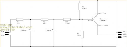
To stop flicker completely you could convert the PWM into an analogue voltage using an RC filter and then use this to drive an appropriately biased transistorEdited by matherp 2015-11-11
WhiteWizzard Guru Joined: 05/04/2013 Location: United KingdomPosts: 2983
Posted: 04:27am 10 Nov 2015
Copy link to clipboard
Print this post
Hi Peter,
Thanks for the 'clues'.
Understand about passing a floating point - easy to rectify this end. Still not got my head around CFunction usage so my mistake - sorry.
Got the point about 62.5Hz pwm at PAUSE 5. I would normally set pwm at 1000 when using the MMBasic built-in PWM channels so hence PAUSE 5 gives a very smooth brightening/diming. Again, easy to sort.
Get the math behind 'resolution' and 1mSec. So RC should be ok to use. I am currently using an NPN to drive a MOSFET to pulse +5v onto the TFT's LED pin (pretty much identical to what you have done on your 'Ultimate Backpack'. Please can you elaborate more i.e. can you provide circuit details/values (or does this depend on the NPN?)
(Am about to try your 'other' PWM mod )
WW
matherp Guru Joined: 11/12/2012 Location: United KingdomPosts: 11435
Posted: 06:34am 10 Nov 2015
Copy link to clipboard
Print this post
Standard transistor biasing. i.e. keeping the transistor in its linear operating range. Note the aggressive RC filter to smooth the slow pulse
This works on the breadboard. The circuit is inverting so 16 is dark and 0 is light
UPDATE What governs the size pictures appear on the BB? Mine always seem to end up small
WhiteWizzard Guru Joined: 05/04/2013 Location: United KingdomPosts: 2983
Posted: 07:11am 10 Nov 2015
Copy link to clipboard
Print this post
Thanks Peter; just what I needed.
I will build it up and give it a go later . . .
WW
twofingers Guru Joined: 02/06/2014 Location: GermanyPosts: 1749
Posted: 07:17am 10 Nov 2015
Copy link to clipboard
Print this post
Pixel size*, I would guess.
Michael
*ie number of pixels.Edited by twofingers 2015-11-11causality ≠ correlation ≠ coincidence
robert.rozee Guru Joined: 31/12/2012 Location: New ZealandPosts: 2526
Posted: 03:14am 11 Nov 2015
Copy link to clipboard
Print this post
using no more than eight 1ms intervals, you can use 'intermediate fractions' to achieve 14 distinct brightness levels from dim (13%) up to full (100%) with the backlight flicker never falling below 125Hz. the only two levels that can not be reproduced are 6% (1/16) and 94% (15/16). see the below table:
for instance, 5/16 (31%) can be approximated by 2/7 (29%). the small error, never exceeding 3%, will be impossible for the user to distinguish.
cheers,
rob :-)Edited by robert.rozee 2015-11-12
matherp Guru Joined: 11/12/2012 Location: United KingdomPosts: 11435
Posted: 03:22am 11 Nov 2015
Copy link to clipboard
Print this post
Rob
I was hoping no-one would suggest that
I did consider it but the coding seemed like hard-work so I went the simple route.
Personally I don't find the 62.5Hz flicker a problem and 8 levels at 125Hz is also good for most applications.
For flicker-free though, the analogue solution above works remarkably well and only needs 1 transistor rather than the transistor and the mosfet I'm using for the switched solution.
If anyone wants to code Rob's solution I'd be happy to implement it.
WhiteWizzard Guru Joined: 05/04/2013 Location: United KingdomPosts: 2983
Posted: 04:04am 11 Nov 2015
Copy link to clipboard
Print this post
What if you have a white background set to BACK1,8? My TFT is really bad, but any other colours seem ok.
WhiteWizzard Guru Joined: 05/04/2013 Location: United KingdomPosts: 2983
Posted: 07:54am 13 Nov 2015
Copy link to clipboard
Print this post
@matherp
I have tried two different TFTs now (both without the RC filter). My original TFT when set to:
BACK 1,8
CLS RGB(200,200,200)
showed exceptionally bad flickering.
I did notice that it was very dependent upon the angle I was viewing the TFT. At some angles the flicker totally disappeared, but if I moved to a different position, it was very (very) noticeable.
The other TFT is 'better' but the flicker is still there.
With the 3v3 RC circuit, I had to omit the 150R resistor as it caused the TFT to be dim at every setting. Without the 150R, the backlight was ok, but too dim for my needs (compared to 5v PWM backlight).
If possible, and also when you are able to do so, can you please post an 8 level,125Hz PWM CSub as mentioned in your first post. Thanks Peter
matherp Guru Joined: 11/12/2012 Location: United KingdomPosts: 11435
WhiteWizzard Guru Joined: 05/04/2013 Location: United KingdomPosts: 2983
Posted: 03:01pm 13 Nov 2015
Copy link to clipboard
Print this post
Thanks Peter. It is just after midnight so will give this a go later this morning when I'm properly awake
Will update in a few hours time . . .
WW
WhiteWizzard Guru Joined: 05/04/2013 Location: United KingdomPosts: 2983
Posted: 02:24pm 14 Nov 2015
Copy link to clipboard
Print this post
@matherp
Your 'untested' code works, but unfortunately I still get flicker with this method.
I have however determined a simple way around the issue. I am using the built in PWM but using a PullUp resistor on the MOSFET so that when the editor is entered, the TFT goes to full brightness (rather than off, which was my main 'concern'). The other downside is that I lose one inbuilt PWM channel.
It turned out that on my worst TFT, I have to use a minimum of 500Hz to not see noticeable flicker for CLS RGB(200,200,200).
I am therefore using PWM 1, 1000, x where x scales nicely from 0 to 100 giving a smooth transition from off to full brightness.
I guess this has highlighted that not all TFTs are 'equal' in terms of 'quality' (i.e. amount of flicker at different PWM frequencies, and also at differing viewing angles). I will run this setup for a few days to see how it holds out; so far it is behaving as I require.
Thanks for your methods posted here. From your explanation I guess 500Hz is not going to be achievable without a lot of work and/or a radical rethink. I am happy with the method I have resorted to apart from the fact it ties up one of the two PWM channels.
WW
kiiid Guru Joined: 11/05/2013 Location: United KingdomPosts: 671
Posted: 04:43am 15 Nov 2015
Copy link to clipboard
Print this post
There is a better method than PWM. I don't know how it is called (or even whether it exists 'officially'). I had to invent it myself some time ago for one of my own designs. Maybe it exists anyway.
Basically it comes down to shifting out suitable bit patterns with 1's and 0's distributed as evenly as possible.
See the C code below. It generates 33 levels of brightness or voltage level with proper output filtering and capacitance, and can work without the flickering effect at frequencies lower than the traditional PWM. The code here is 'raw' and not translated for MM, but maybe someone can give it a try.
The most important part of it is the array of 33 'magic' bit patterns which I have spent long time working on.
// call this function periodically with frequency as high as possible
// (level) is the required magic PWM output level 0...32
// 'PORT' is the output port line