
|
|
Forum Index : Microcontroller and PC projects : MM+: TFT Backpack PCB for 100-pin
| Author | Message | ||||
| matherp Guru Joined: 11/12/2012 Location: United KingdomPosts: 11435 |
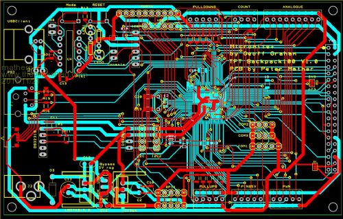
I've designed a PCB for the 100-pin MM+ to use as a development environment. The PCB is exactly the same size as a 5" SSD1963 display so that it can be bolted directly to the back of the display (hopefully the holes align). Like the 64-pin version this uses Microblock's firmware for a PIC16F1455 as the USB interface and as an on-board programmer for the PIC32MX470F512L The design only supports the parallel displays SSD1963 (any size) or SSD1289 modified for 8-bit operation. To keep things simple the backlight can either be controlled in software using the MM+ firmware (SSD1963 only) or is just selectable between 3.3 and 5V. Every pin on the MM+ is broken out for use. These are grouped into semi-logical blocks. 18 pins for TFT, SDcard, Touch pins connect to the 40-pin header (LCD-D0 to LCD-D7, WR, RS, RESET, optional RD, touch IRQ, touch CS, SD CS, SPI2 in, out and clock) 9: analogue pins 4: count/frequency pins, including optional pullup for IR use 5: PWMm pins 5: digital I/O pins with optional pulldown resistors 5: 5V-tolerant digital I/O pins 5: digital I/O pins with optional pullups 8: PORTA pins for use with parallel bus peripherals 3: headers with the SPI pins + GND + 3.3V 2: headers with the i2c pins + GND + 3.3V 3: Com1 header including com1-enable pin 2: Com2 header 2: Com3 header 2: console/com4 header if PIC16F1455 is not in use 2: PS2 Keyboard connector 3: micro-usb connector, this includes the USBID pin for future use headers for the DS3231 RTC module ICSP header optional external or USB power Note the analogue, count, pulldown, pullup, 5V and PWM headers are three row with GND and power connections available to each I/O pin. Power is 5V for the 5V tolerant pin header and the PWM header allowing direct connection of a standard servo with no additional wiring. All other headers use 3.3V power. 2015-11-21_181118_Backpack100schematic.pdf 2015-11-21_181133_Backpack100layout.pdf Still to do is to include all the pin numbers on the silkscreening. As this is a rather large board (84mm x 135mm) it will be a bit more expensive to have made (circa USD6 each) than the smaller variants so I haven't yet decided to go ahead. Please let me have any comments/suggestions and if you would like one (or more) send me a PM and based on response I'll decide whether to go ahead. |
||||
bigmik Guru Joined: 20/06/2011 Location: AustraliaPosts: 2981 |
Peter, Another great effort on your part. I know you designed this to be the same size as a 5" LCD panel but it looks to me that it wouldn't be too difficult to reduce the width to 100mm, then you could drop the manufacturing price down to around $2.20US landed (snail mail) or $3.30US (DHL).. Prices based on Shenzhen2U.com price guide Anyway great job as usual. Regards, Mick Mick's uMite Stuff can be found >>> HERE (Kindly hosted by Dontronics) <<< |
||||
Grogster Admin Group Joined: 31/12/2012 Location: New ZealandPosts: 9974 |
Nice board, Peter. 
You like ASAP(As Small As Possible!) PCB's, don't you Mick!   Smoke makes things work. When the smoke gets out, it stops! |
||||
| bigmik Guru Joined: 20/06/2011 Location: AustraliaPosts: 2981 |
Hi Grogs, All, Hmm, is there an innuendo hidden there?? Actually yes and no, I like small because they can be produced very cheaply, once you go beyond 10cm in any direction the costs go up astronomically unless you order 100 QTY. There is merit in spacing components out as it allows a region of isolation from other components and allows easier fault testing and measurements.. But that comes at a cost. Small is generally my preference (no puns to be seen here) as it keeps costs low and also allows the boards to be more easily hidden in other equipment. It is horses for courses, I made the suggestion as an observation not a criticism. Regards, Mick Mick's uMite Stuff can be found >>> HERE (Kindly hosted by Dontronics) <<< |
||||
| Grogster Admin Group Joined: 31/12/2012 Location: New ZealandPosts: 9974 |
No offence, Mick - I was just ribbing ya!
I know why you want small PCB's, and for minimizing costs, you are quite correct there. I was just getting the boot in while I could. Smoke makes things work. When the smoke gets out, it stops! |
||||
| bigmik Guru Joined: 20/06/2011 Location: AustraliaPosts: 2981 |
Grogs, Grrrrr,, Damn Kiwi Rugby supporters... Not only kicking a poor cousin while he is down but running away with my PCBs and laughing at me as well...  (reference to a silly lost bet to those not in the `know') (reference to a silly lost bet to those not in the `know')
I'll get you butler......
Of course no offense cobber... See you in the soup.. Mick Mick's uMite Stuff can be found >>> HERE (Kindly hosted by Dontronics) <<< |
||||
| The Back Shed's forum code is written, and hosted, in Australia. | © JAQ Software 2026 |
