
|
|
Forum Index : Microcontroller and PC projects : Mains Fail Detector...
| Author | Message | ||||
Grogster Admin Group Joined: 31/12/2012 Location: New ZealandPosts: 9986 |
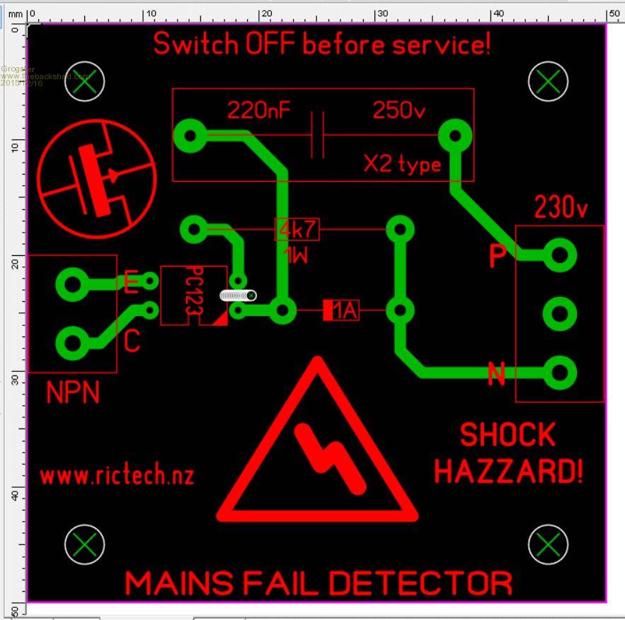
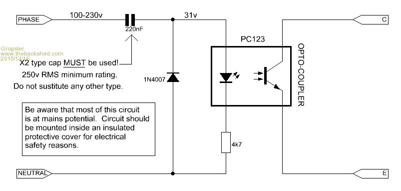
I often need to find out if a source of mains has failed. This is a copy of the circuit that can be found all over Google if you search for "LED on the mains", but with a couple of vital changes - X2 type mains cap and opto-coupled output for isolation. I guess I should mention at this point, that this circuit is only for those who are aware of the dangers of working with the mains, and who will take suitable safety precautions while working with this circuit. This thread is not intended for anyone not happy and competent working with the mains voltage. There may also be electrical compliance issues depending on where you are on the planet. 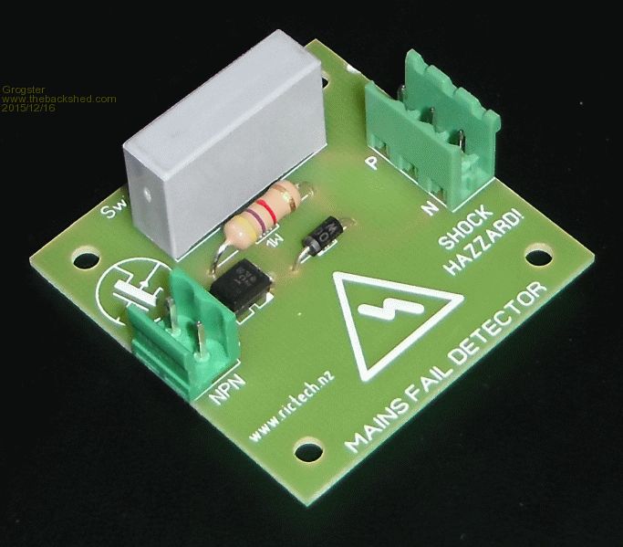
The opto-isolated output can be directly interfaced to any MM or other project: 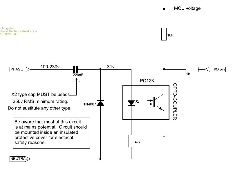
With mains present, the opto pulls the I/O pin low. If the mains fails, the I/O pin goes high via the 10k/1k combination, and this can be detected with your code or an interrupt on the MM series of MCU's. Placed inside a small plastic box, this unit can provide an isolated NPN output for any project needing to detect when the main power has failed. Smoke makes things work. When the smoke gets out, it stops! |
||||
| VK2MCT Senior Member Joined: 30/03/2012 Location: AustraliaPosts: 120 |
I'm thinking the output is a 50hz square wave. Is this true ? John B. |
||||
| Grogster Admin Group Joined: 31/12/2012 Location: New ZealandPosts: 9986 |
Yes, I would expect so, as our mains is 50Hz. Used in America, the output would be a 60Hz square-wave. Depending on how quick you are monitoring things, a small cap might be needed across the NPN to "Smooth" things if you are using an interrupt to monitor the pin or it will be forever self-tripping at the mains frequency.... 
EDIT: Yes, it most certainly is..... 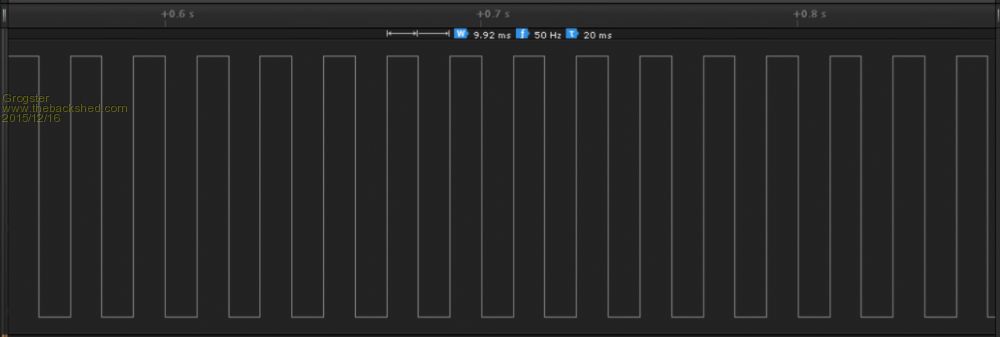
I expected that to be the case though. Smoke makes things work. When the smoke gets out, it stops! |
||||
jman Guru Joined: 12/06/2011 Location: New ZealandPosts: 711 |
Hi Here's a thought why not just use a mains powered relay (continuously rated)mains goes away the relay turns off :) then do whatever with the contacts Jman |
||||
| MicroBlocks Guru Joined: 12/05/2012 Location: ThailandPosts: 2209 |
A continuously powered relay will fail. Adding a cap would be enough to make that signal high all the time. But then again, why should it be, connect it to a count pin and count the pulses. If it is zero, mains is off. If it is around 50/sec, mains is on. You could even display the count to give you an indication of the Hz. Even clocks can use it as a timing signal. Microblocks. Build with logic. |
||||
| atmega8 Guru Joined: 19/11/2013 Location: GermanyPosts: 738 |
This circuit, as the most of capacitiv Power Supplies, is missing a MOV in the input between neutral and Phase. This the number 1 reason for failing X2 capacitors, because of very ugly transients.... Add it to the circuit for safety and stability. infos |
||||
| Grogster Admin Group Joined: 31/12/2012 Location: New ZealandPosts: 9986 |
@ jman & microblocks - Exactly right. I have used relays with 230v coils before, but they tend to run hot when running all the time, and they DO fail as microblocks has said. However, that is certainly an option I have used in the past. @ atmega8 - good point, well made.  I will add one. I will add one.Smoke makes things work. When the smoke gets out, it stops! |
||||
| atmega8 Guru Joined: 19/11/2013 Location: GermanyPosts: 738 |
Furthermore, please put a resistor of 2k2 in Series with the poor and stressed X2! Also parallel resistor to the X2 is a Must ( 1 MEG ) |
||||
| Grogster Admin Group Joined: 31/12/2012 Location: New ZealandPosts: 9986 |
Why is the X2 stressed? An X2 cap is rated to be connected directly across the mains, so I don't see any obvious stress issues. Or are you referring to what happens to it during a transient condition? Why is the 1M in parallel with the X2 a must? It isn't here - perhaps your regulations are tougher though.... Smoke makes things work. When the smoke gets out, it stops! |
||||
| jman Guru Joined: 12/06/2011 Location: New ZealandPosts: 711 |
Hi G You feeling brave try this from Microchip Are you mad BTW I have a 220v Relay that's been on for over 5 years and still going Jman |
||||
| atmega8 Guru Joined: 19/11/2013 Location: GermanyPosts: 738 |
The Microchip pdf is exactly The one i referenced under the info link. Here are the answers for brave Grogster in theory and Praxis ;-). The First design is dangerous the chance for a failing X2 is very high. The electrical shock by touching the Main plug Leads directly to jail.... |
||||
BobD Guru Joined: 07/12/2011 Location: AustraliaPosts: 935 |
If I had a need for a circuit for this purpose I would use a small transformer to do the job. There are many around with good primary to secondary isolation and it's possible to keep your mains voltage off the PC board by directly connecting to the transformer primary leads. An excellent application for a couple of layers of heat shrink tube. As Jman says, a good mains relay will go the distance. They are used all over the place as machinery contactors. However, unless you get a freebie then the transformer is likely to be cheaper. |
||||
| Grogster Admin Group Joined: 31/12/2012 Location: New ZealandPosts: 9986 |
What brand/type of relay are you guys referring to with a 230v coil? The ones I used were Omron brand, were brand new, and both died within six months of each other. Either crap brand, or perhaps crook batch of relays or something? Smoke makes things work. When the smoke gets out, it stops! |
||||
| MicroBlocks Guru Joined: 12/05/2012 Location: ThailandPosts: 2209 |
If you have a choice between mechanical parts and solid state then it is solid state 100% of the time. For large industrial use it is probably cheaper (or the only way) to use mechanical relays because the large currents. For only monitoring you need a tiny little bit of current, so an optocoupler is a perfect way to do it. Getting the voltage down safely can be done in many different ways. Just using a resistor (or better more than 1 resistor) is sufficient. An even easier way is to use a part that is specifically made for that purpose.Like the https://www.fairchildsemi.com/datasheets/MI/MID400.pdf Microblocks. Build with logic. |
||||
| skyv Newbie Joined: 14/03/2015 Location: AustraliaPosts: 14 |
Perhaps an old phone charger, just monitor the 5 volt output. skyv |
||||
| Grogster Admin Group Joined: 31/12/2012 Location: New ZealandPosts: 9986 |
Thanks for the PDF - that looks like an interesting device. I am reading it now... Smoke makes things work. When the smoke gets out, it stops! |
||||
| WhiteWizzard Guru Joined: 05/04/2013 Location: United KingdomPosts: 2991 |
@MicroBlocks As Grogs has already said; 'thanks' for posting that part's pdf. A little pricey for an IC but this is much cheaper than other options I have looked at in the past. I notice the datasheet is dated 2005 so it has been around for a while!! Have you actually used the MID400 in anything? If so, how did it perform for your application. I think I will order a couple in and give them a try. Thanks again . . .
WW |
||||
| Grogster Admin Group Joined: 31/12/2012 Location: New ZealandPosts: 9986 |
Yes, I too have decided to get some. NZ$7 each from Element 14, or cheaper on eBay for NZ$13.50 for ten - link True, but still good value. The Omron relays were forty-something bucks each, so even at Element 14's $7 price.... Smoke makes things work. When the smoke gets out, it stops! |
||||
| MicroBlocks Guru Joined: 12/05/2012 Location: ThailandPosts: 2209 |
Yep, used them in two projects and they perform good (still do as did not get a complaint yet.:) ) They might be a bit pricy but they are so simple to use and you need only a few extra parts. Mine worked with a 5v mcu, i am not sure it works with 3.3v. Check the datasheet to make sure. Microblocks. Build with logic. |
||||
| The Back Shed's forum code is written, and hosted, in Australia. | © JAQ Software 2026 |
