
|
|
Forum Index : Microcontroller and PC projects : Water proof distance sensors
| Page 1 of 2 |
|||||
| Author | Message | ||||
| Bizzie Senior Member Joined: 06/07/2014 Location: AustraliaPosts: 192 |
Hi all, Has anyone used any of the cheap water proof distance sensors, like this one . I am going to ask these sensors to work in a very harsh (read dusty) environment on a combine harvester (Auto header for us Ozies) to measure how much grain is in the bin. I am also assuming that the distance function will work on these also. Any comments would be appreciated. Rob White |
||||
| Gizmo Admin Group Joined: 05/06/2004 Location: AustraliaPosts: 5182 |
Could be a interesting project. It would be a very dusty environment, so not sure how well the sensor will determine distance through the dust, onto a soft surface like grain. I guess the only way to know if through experimentation. Could you weigh the bin? Glenn The best time to plant a tree was twenty years ago, the second best time is right now. JAQ |
||||
| Bizzie Senior Member Joined: 06/07/2014 Location: AustraliaPosts: 192 |
While it is very dusty, I do not think it will be a problem as far as the measurements are concerned. I am not so sure about ingress of fine dust into the sensor. As far as a soft surface is concerned I will test with wheat tomorrow. It works fine with calf pellets! I could just use paddles and micro switches as most manufacturers use but this only gives spot readings I hope with a series of sensors I can build a more detailed "picture" of what is in the bin. It is not feasible to use weight cells as the bin is almost a structural part of the header. There is data available as to how much grain is being harvested but it is near on impossible to get into the CAN bus because of propriety encoding of the messages. Regards Rob Rob White |
||||
TassyJim Guru Joined: 07/08/2011 Location: AustraliaPosts: 6536 |
It looks the same the ones I use for my water tanks. http://www.ebay.com.au/itm/201372160358 My sensors are in the top of the water tank so not dusty but very high humidity. I mounted them in the end of a piece of conduit and plenty of silicon sealer to hold the conduit in place. The concrete tank is fine but my polly tank expands in the heat so there is a ~1cm variation between day and night readings. They work with the micromite firmware without any problems. The only time I had a bad reading was with a poor contact where the sensor plugs into the circuit-board. They have been in place for about 12 months. You can buy the sensors in sets of 4 so spares would be cheap if you find they do not last. Jim VK7JH MMedit |
||||
bigmik Guru Joined: 20/06/2011 Location: AustraliaPosts: 2981 |
GDay Jim, All, Happy New year to you all and your family. I have just ordered a waterproof sensor similar to your one. Jim, I am wondering just what you use to display your display water level? I have a 2200lt tank (nothing compared to yours no doubt) but it is a tall (about 2.5m and skinny (500mm) unit.. We use it to water the garden bed... I was thinking of small uMite that either displays a bargraph of the water level (you can get a nice array that has about six green and the rest yellow and red) so as a level reader it could be go, or I have considered an LCD to display the water level remaining in `calculated' litres.. Just wondering what you have chosen.. Now, also do you know what happens when the water level is too close to the sensor.. the specs say (or seem to say) BLIND at less than 25cm... I am happy if it doesnt tell me that there is 2000 to 2200lt there, I can just say `2000lt PLUS'. Now I intend to either run at a low frequency and have it on all the time with maybe a small lead acid battery topped up via a solar panel or I do have 240v there for the pump.. Just interested in other setups and how they have been managed. Regards, Mick Mick's uMite Stuff can be found >>> HERE (Kindly hosted by Dontronics) <<< |
||||
| TassyJim Guru Joined: 07/08/2011 Location: AustraliaPosts: 6536 |
Hi Mick, My level sensors are part of the big picture. When full, the distance to water is about 27cm for both tanks and that seems reliable. You might be able to fit a 100-150mm piece of 90mm pipe to the top as a chimney and mount the sensor a bit higher if you need the extra room. You will get a -1 error if the water gets too close. If your tank is polly, it will probably expand in the sun and raise the sensor a bit, so expect some strange readings. I have been a bit slow in putting it all together. New options keep appearing so I keep changing my mind about displays etc. I log everything to a PC and have a program giving graphs. I need to add the new sensors to the graphs. I also will have a few remote displays for various readouts. I will have a 2.4 inch display in the house for the Boss to use. It will show indoor/outdoor temperature/humidity normally and switch to rain (if we are ever that lucky again). She wants days since last rain etc. There is another screen for hothouse conditions. It will also have a water screen which shows levels (as a percentage) and flow rates. I am not game to let her know that I record how much water she uses in the shower. Current count is 7 remote sensor modules (micromites) and the master (Colour Maximite) linked with 100m of cat5 and one RF link. I might end up with a 7in display for the master control or stick with the PC. I have remote access so we can monitor things when traveling. Today the bore has pumped 7768L and the garden has been given 5281L Yesterday used a lot more. Your tank wouldn't last long! Jim VK7JH MMedit |
||||
| Bizzie Senior Member Joined: 06/07/2014 Location: AustraliaPosts: 192 |
Hey great to see the comments re water tanks! I was thinking of either a bar graph or pie graph for grain level. I am not sure how easy my operators might interpret the pie graph though. What I did not say in the original post is that this data will be transmitted to the "Chaser bin" driver as well as in the header. Seeing graphics are so simple on the MM+ I have also thought about a cross section of the bin, it is not regular in shape, hence my use of multiple senors. Jim another question arising from your post. You mention volume is that just calculated values or do you have flow sensors on your pump? If flow sensors what type? Rob Rob White |
||||
| TassyJim Guru Joined: 07/08/2011 Location: AustraliaPosts: 6536 |
This is the flow sensor I use http://www.ebay.com.au/itm/281703872774 It is 3/4 inch and 1-60 L/min. There are other sizes available but that one suits my domestic volumes. I did have some Jaycar ones but they failed after 2 years and cost a lot more. I hope these ones last longer. Jim VK7JH MMedit |
||||
| CaptainBoing Guru Joined: 07/09/2016 Location: United KingdomPosts: 2171 |
deleted |
||||
| CaptainBoing Guru Joined: 07/09/2016 Location: United KingdomPosts: 2171 |
Hi Jim. I have a question. I have two of these (look identical) but they are outputting a serial data stream and are self triggering - 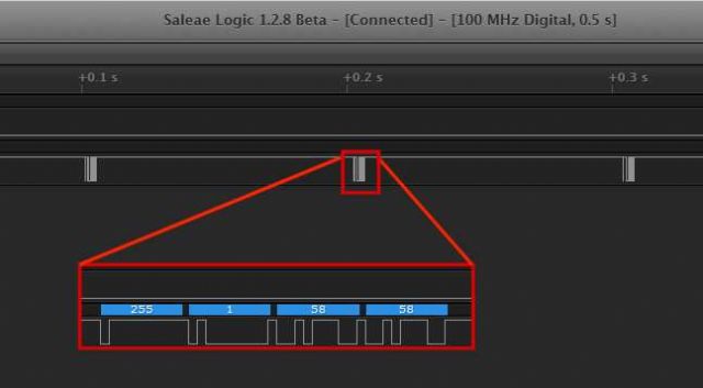 They are definitely not PWM in the conventional sense. The data stream always starts with 255, the next byte is usually a 1 but I have seen 3 and 6. The last two bytes are usually the same and do change with the distance from the object - that said they are all over the place. I have looked everywhere for a data sheet but can't find one - can anyone help? |
||||
| TassyJim Guru Joined: 07/08/2011 Location: AustraliaPosts: 6536 |
If they are outputting a serial stream, they are not the same as mine. The transducers might be the same but the logic board is very different. Do you have a link to the ones you have? Jim VK7JH MMedit |
||||
| bigmik Guru Joined: 20/06/2011 Location: AustraliaPosts: 2981 |
Hi Cap'n, I have mine working really well in my 2200lt tank, BUT I did have a lot of issues initially,, I mounted my original into the end of an inverted plastic pot and the sensor was about 27cm above the max water line... I cut a hole the dia of the opening of the pot and I found it extremely intermittant.. Would work this morning but not tonight or vice versa or work for a few days and then not for a week,,, It drove me (and my Missus) Mad... It was funny as I could test inside the house to a wall and it would work until the sensor was about 22cm from the wall.. This never failed... I read the sensor sends a beam of 50 degrees and my pot probably was not large enough (though it worked against the wall) so I eventually mounted the sensor into the eaves (made distance from max level of tank 32cm) and used a larger pot (and of course larger opening into the tank) and it now has been working flawlessly (better check I bet it wont work now that I said that) for a few months..... I suspect that I was getting echos bouncing around as the water surface was rippling and these reflected off the smaller pot... I didn't try a PVC pipe but the 50degree angle of transmission would mean that the pipe would have to be limited in length to about 50mm. Or so (in my case top of tank to top of water when full was 11cm) so I would have needed 15cm + of tube... I am happy to post my code if you want, calculates distance measured and then converts to volume and draws a neat BAR graph... But of course we all know how bad my coding is.. and YES it uses GOTO and GOSUB (I think) Regards, Mick Mick's uMite Stuff can be found >>> HERE (Kindly hosted by Dontronics) <<< |
||||
| TassyJim Guru Joined: 07/08/2011 Location: AustraliaPosts: 6536 |
Mick, I get a few stray readings with mine, mainly when I am pumping from the bore, so I am going to experiment with a long length of 90mm pipe as a stillwell. Jim VK7JH MMedit |
||||
| CaptainBoing Guru Joined: 07/09/2016 Location: United KingdomPosts: 2171 |
This is the link for them from ebay and the controller looks the same as the one you posted originally. Here are some close-ups of the board - the two ICs are un-marked (of course) 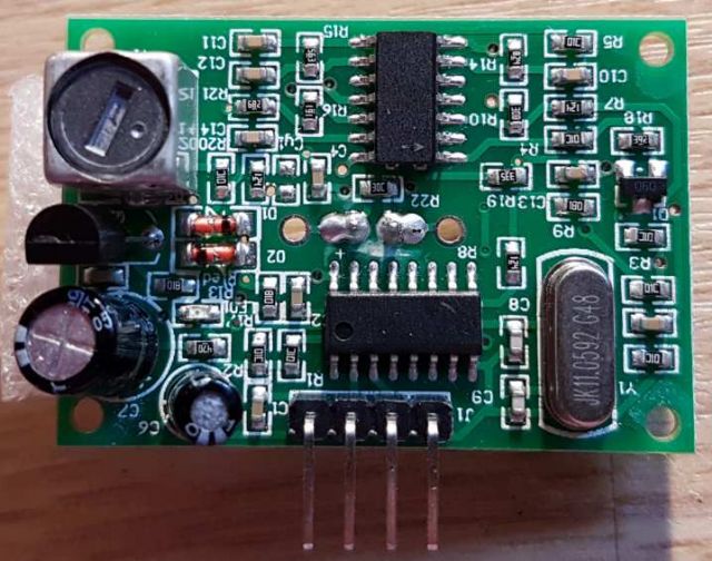 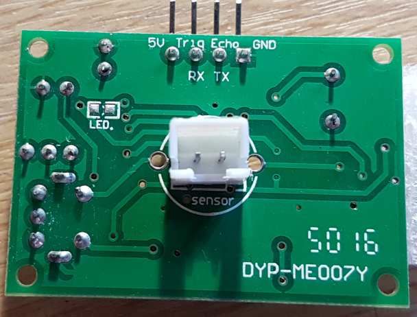 Initially I expected them to be PWM devices. I bnotice the tiny green LED flickering as soon as they got power, wrote some code with the Distance CSUB and got a stream od -2's with the occasional 16.7 or similar... took the device out and replaced it with the test "twin can" stylee and the code worked immediately. Got my analyser on the teo pins and saw the trigger pulse seemed to have nothing to do with the echo pin... stopped the code and the pulse train continued. Zooming in, it looked familiar so i applied a serial analyser and got the previous screen shot on one of them. I chaged the code and linked the "exho" pin (which is also labelled TX) to COM1 and wrote some code and got this from it: 1 100 100 1.72414 1.36638 1 119 119 2.05172 1.38966 1 91 91 1.56897 1.40086 1 90 90 1.55172 1.39138 1 101 101 1.74138 1.40172 1 79 79 1.36207 1.39655 1 111 111 1.91379 1.41897 1 89 89 1.53448 1.42155 1 82 82 1.41379 1.41034 1 95 95 1.63793 1.42672 1 98 98 1.68966 1.43448 1 81 81 1.39655 1.40862 1 90 90 1.55172 1.39052 1 94 94 1.62069 1.4 1 101 101 1.74138 1.40603 1 108 108 1.86207 1.44138 1 24 24 0.413793 1.40431 1 26 26 0.448276 1.40431 1 80 80 1.37931 1.45172 1 110 110 1.89655 1.525 first column is the byte immediately after the 255, then the two numbers. I thought these might be microseconds or somehow related with the "1" but my SoS calculation (col4 and averaged over 5; col5) don't really reflect the distance - even given for echoes... Moving the sensor does vary the numbers but they are only ever "in the zone"... which I might expect for a closed environment - much the same as you found with the echoes from your water tank. Currently, I am lost pending a PDF - I have crawled through so many pages but you can imagine the hits I get for Ultrasonic, serial, Not PWM... etc.  cheers all for reference, here's the test prog - no finesse and a few GOTOs  Option base 1 Const l=20 Dim integer c Dim float d(l),v For n=1 To l:d(n)=5:Next Open "com1:9600,1024" As #1 main: ' Print Loc(#1) If Loc(#1)<>0 Then c=Asc(Input$(1,#1)) If c=255 Then ' sync on 255 Do:Loop Until Loc(#1)>2 ' wait for the next three chars to arrive c=Asc(Input$(1,#1)) Print c, 'If c<>1 Then GoTo badframe c=Asc(Input$(1,#1)) ' two reads to flush the buffer Print c, For n=2 To l:d(n-1)=d(n):Next c=Asc(Input$(1,#1)) Print c, d(l)=c/58 Print d(l), v=0 For n=1 To l:v=v+d(n):Next Print v/l End If End If badframe: ' If Loc(#1)<>0 Then a$=Input$(Loc(#1),#1) GoTo main |
||||
| CaptainBoing Guru Joined: 07/09/2016 Location: United KingdomPosts: 2171 |
Hi All. I have done a bit more fiddling with this and I have come to the conclusion that the output is a direct reading of milimeters. Let's call the four bytes S,a,b,b' (Sync, a,b and b prime) S=255, always. b' is always b +/- a few I have a rough correlation of a*256 + ((b+c)/2) as millimeters (I actually converted to cm just to stabilize the readings a bit). It definitely seems to be giving in the right area. sometimes (haven't been able to pin it down yet) the sensor drops to around 40cm and then that is it - I have to power cycle the unit to get it back - the trig input doesn't seem to do anything HI or LO but then I suspect it is just the RX input on the micro-controller near the plug. It seems like it is some sort of time-out. I have seen times of 82 seconds and another of 177... if this is aimed at the automotive industry it may be a way of drawing attention to the vehicle left in reverse for a prolonged period. EDIT found this site which does briefly detail the output format (love Chinglish  ) )" Explain: Each time the module outputs a frame, including4individual8Bit data, frame format:0XFF+H_DATA+L_DATA+SUM 1,0XFF:Start data for a frame to judge. 2,H_DARAHigh distance data.8A. 3,L_DATALow distance data.8A. 4,SUMData and for cross examination. his0XFF+H_DATA+L_DATA=SUM(only low8A) 5,H_DATAandL_DATASynthesis16Bit data, that is, the distance value of the unit. " but still no clue as to why it packs up after a while - both units do. hmmm... still missing something |
||||
| isochronic Guru Joined: 21/01/2012 Location: AustraliaPosts: 689 |
There was an article in silicon chip, in the "reusing cheap modules" vein. I don't remember many details, but one chip is a max232 type, drives the sender after trigger goes (high?). The other is a 4x opamp in a filter, detects a received burst of 8 pulses. Output goes high (? check) after a time corresponding to distance - the article has the formula. (ed) the usual type has two transducers but I think the board is using one to send and then receive...and the serial i/o uses the trigger and receive pins ?! weird.. |
||||
| CaptainBoing Guru Joined: 07/09/2016 Location: United KingdomPosts: 2171 |
Thanks for this - I will see if I an track it down. You are right about the 14 pin chip - it is LM324. |
||||
| isochronic Guru Joined: 21/01/2012 Location: AustraliaPosts: 689 |
I am thinking "serial" is a translation effect maybe |
||||
| TassyJim Guru Joined: 07/08/2011 Location: AustraliaPosts: 6536 |
Now I am confused. The photos a few posts back show the same units I have. A pulse on the trigger starts it and the length of the echo pulse determines the distance. I have used units with 2 transducers as well as units with one. I have also used units with the trigger and echo pins combined. The MMBasic function will work with all BUT as usual, there are a few modules out there in Ebay land that are different. Just because they like being difficult. The unit referred to in the later post and with the link to aliexpress is talking about a different module that does have serial output. One of the photos in the link seems to show my twin transducer unit but there is no way it outputs serial data. Jim VK7JH MMedit |
||||
| CaptainBoing Guru Joined: 07/09/2016 Location: United KingdomPosts: 2171 |
I agree totally Jim. I was expecting these to run just like yours however I was getting weird results returned buy the Distance() function - I must confess I expected that the CSub awas corrupted somehow (its not in the main build on V5.04). Plugging in the old test unit I had with the code un-altered gave me the results I was expecting. I scoped the inputs and outputs and noticed the TRIG input didn't seem to have any relevance to the output which was a pulse train and not the expected single pulse with proportional width. I can only assume there is different firmware in the on-board controller and hunting around I can see that there is an option for either with some vendors. Caveat emptor I guess I have a case with the seller as his auction didn't give any indication of output type, but he is likely just a box-shifter. Chancing my arm on getting them refunded but nothing ventured nothing gained. If the output was constant I could probably use them and the biggest problem of all is that they just drop from reading, say, 1.4m to around 40cm... nothing moved, same software running in a loop and then it is an arbitrary amount of time to "reset". If I don't get them refunded, I'll send you one to play with. |
||||
| Page 1 of 2 |
|||||
| The Back Shed's forum code is written, and hosted, in Australia. | © JAQ Software 2026 |
